Connector system for solar cell roofing tiles

a solar cell and connector technology, applied in the direction of photovoltaic supports, coupling device connections, sustainable buildings, etc., can solve the problems of tool misalignment with the connector, tend to break the furcated member in the field, etc., to achieve good alignment, low profile, sealing and heat dissipation

Inactive Publication Date: 2008-06-17
TE CONNECTIVITY CORP
View PDF16 Cites 113 Cited by
  • Summary
  • Abstract
  • Description
  • Claims
  • Application Information

AI Technical Summary

Benefits of technology

[0009]It is an advantage of the present invention that it provides a lower-cost termination solution with good alignment, sealing, locking and heat dissipation, and which is accomplished without the use of a tool for making the terminations.
[0010]Another advantage of the present invention is that it includes a conventional reliable termination interface having a flat male push-on terminal with a positive latch-locking feature.
[0011]A further advantage of the present invention is that it employs a proven termination contact interface with push-on blade termina

Problems solved by technology

However, in addition to the inconvenience of requiring a roof installer to carry an expensive extra tool, these furcated members tend to break in the field because of the relatively low force re

Method used


Image

  • Connector system for solar cell roofing tiles
  • Connector system for solar cell roofing tiles
  • Connector system for solar cell roofing tiles

Examples


Embodiment Construction

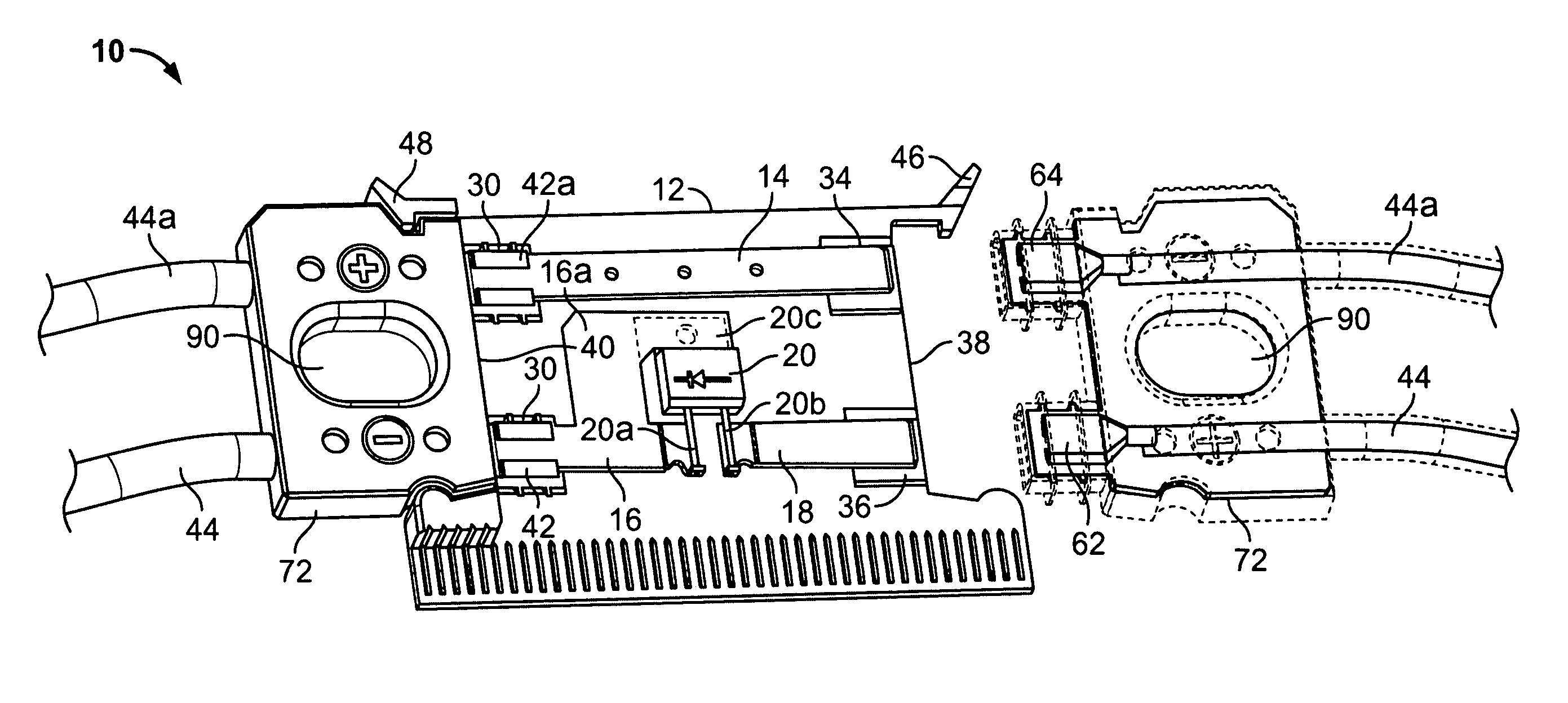
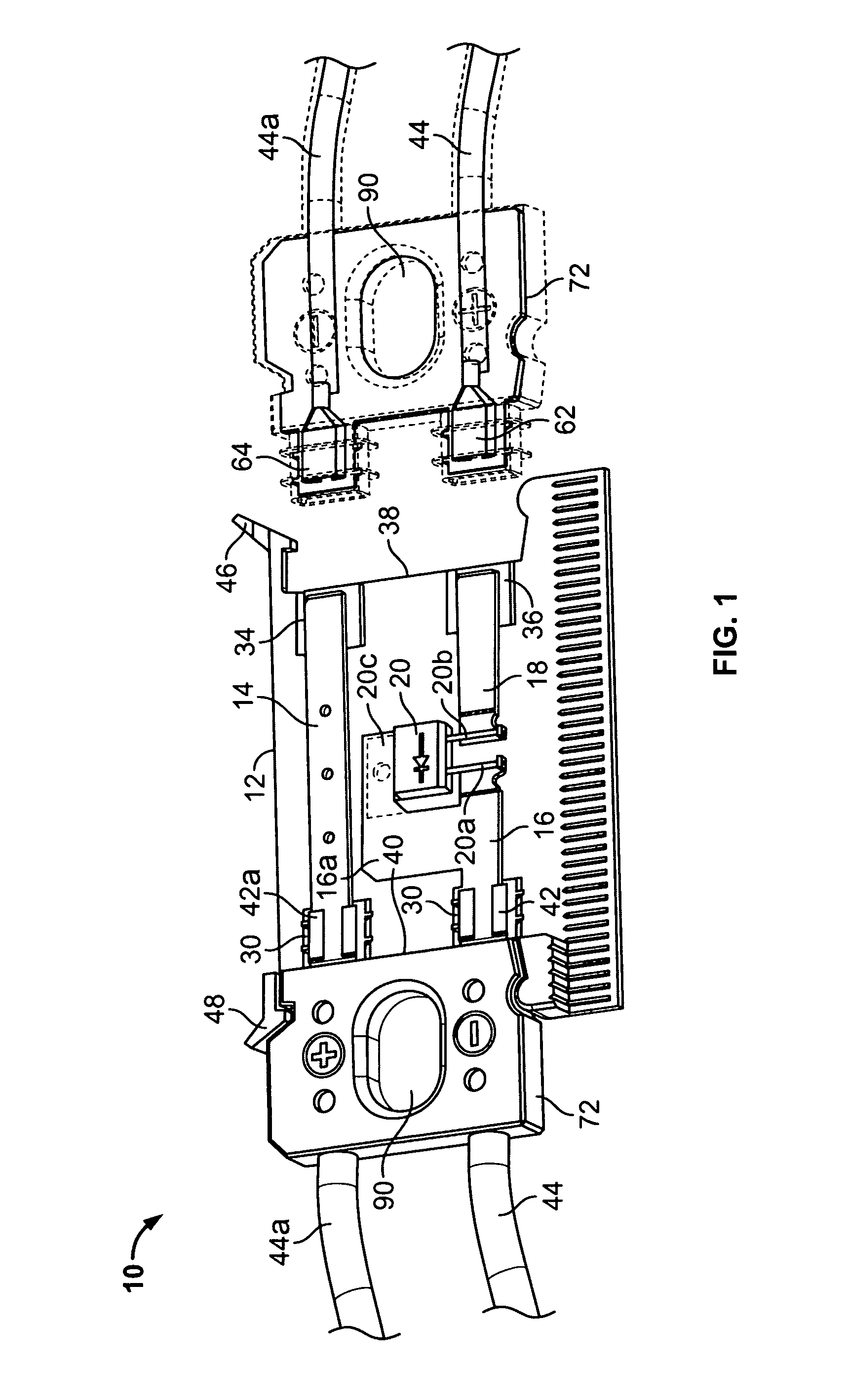
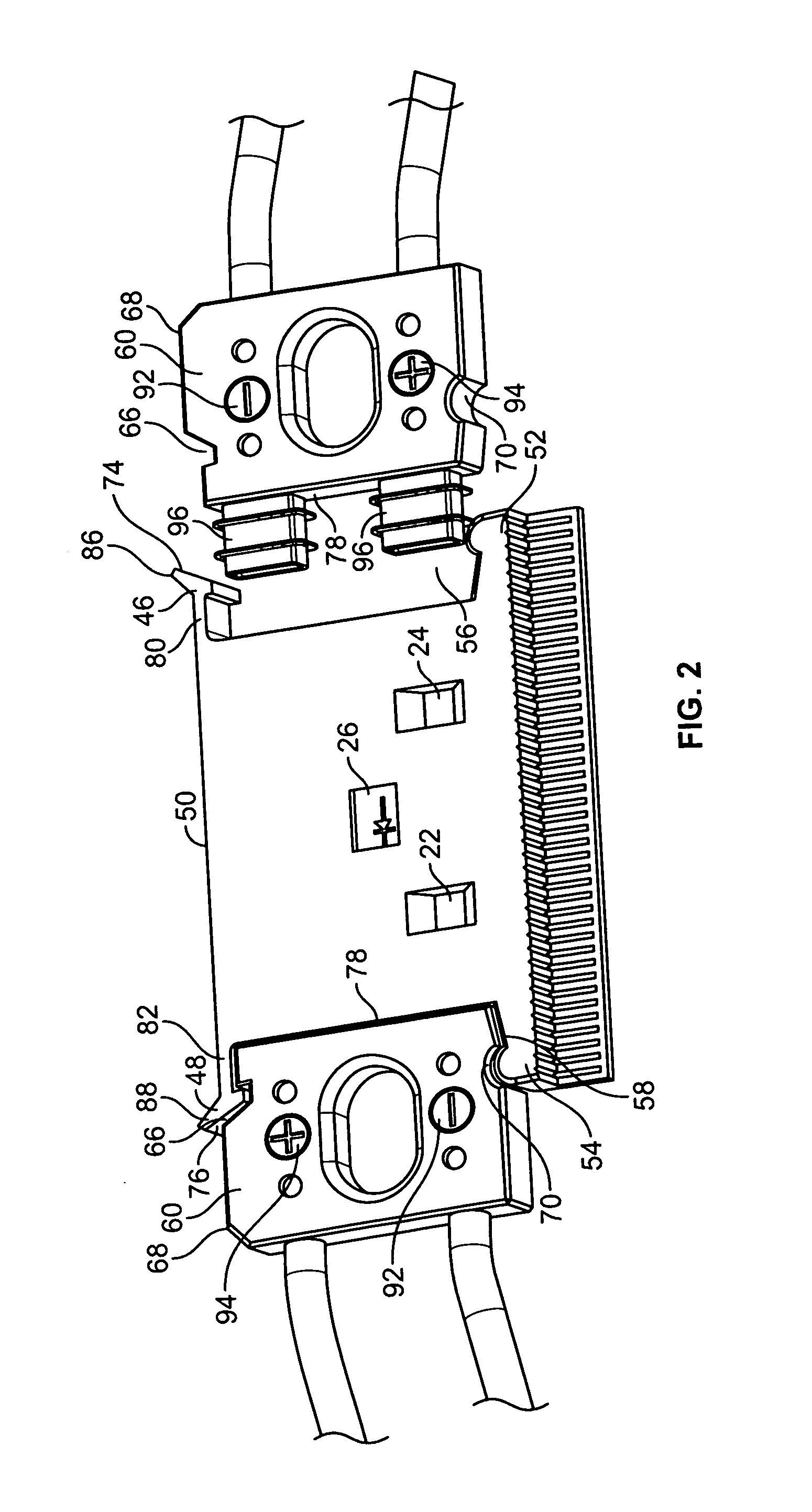
[0022]Referring to FIGS. 1 and 2, an electrical interconnection system is generally designated as 10. A connector body 12 houses internal conductor portions 14, 16 and 18, a diode assembly 20, and apertures 22, 24 and 26. Apertures 22, 24 are provided on the back or downward facing side of the connector body 12 to enable soldering tabbing to the PV panel and aperture 26 is provided on the back or downward-facing side of the connector body 12 to provide a vent for the diode for heat dissipation. Preferably, the conductor portions 14, 16 and 18 and diode 20 are insert molded in the connector portion 12. One contact portion 16 or 18 may include an integral flag-shaped portion 16a forming a right angle around the diode 20, for contacting the heat sink 20c of the diode 20. The flag portion 16a provides additional heat dissipation surface with the heat sink 20c.

[0023]The conductor portions 14, 16&18 extend into recesses 30 and 32, or 34 and 36 at either end 40, 38, respectively, of the c...


PUM


Abstract

A connector system for photovoltaic roof tiles has a body and a plug assembly with latching means. The body portion has a latching member and a rib defining a recess for mating with the plug assembly. A pair of cavities extends inwardly from the recess. The latching member has a projection, and integral conductors are formed within the body portion. The plug assembly has an indentation for retentively receiving the projection, and an indentation for receiving the rib. A pair of protrusions extends from a peripheral end of the plug assembly and receives a cable terminal of the plug assembly. The protrusions engage with and seal off the cavities to form an electrically conductive path with the cable terminals when the body and the plug mate. The latching projection retentively engages the plug. The plug assembly disengages by manipulation of the latching member projection member.

Description

FIELD OF THE INVENTION[0001]The present invention is directed to an electrical interconnection system, and more particularly to an electrical interconnection system for photovoltaic energy arrays installed in roof tile systems.BACKGROUND OF THE INVENTION[0002]Photovoltaic (PV) modules or arrays produce electricity from solar energy. Electrical power produced by PV modules reduces the amount of energy required from non-renewable resources such as fossil fuels and nuclear energy. Significant environmental benefits are also realized from solar energy production, for example, reduction in air pollution from burning fossil fuels, reduction in water and land use from power generation plants, and reduction in the storage of waste byproducts. Solar energy produces no noise, and has few moving components. Because of their reliability, PV modules also reduce the cost of residential and commercial power to consumers.[0003]PV cells are essentially large-area semiconductor diodes. Due to the pho...

Claims


Application Information

Patent Timeline
IPC IPC(8): H01R13/66
CPCH01R13/6272H02S40/345H02S20/25H02S40/34H01R13/5219H01R13/6641Y02B10/12Y02E10/50Y02B10/10
Inventor DAILY, CHRISTOPHER GEORGEDUESTERHOEFT, SCOTT STEPHEN
Owner TE CONNECTIVITY CORP
Why Eureka
Try Eureka