Control method for external control type fan clutch

a control method and fan clutch technology, applied in the direction of electric control, engine starters, machines/engines, etc., can solve the problems of not being able to optimize the fan rotation control, the engine speed or the state of the fan clutch, and not being able to properly respond to the variations of the fan speed, etc., to improve the cooling performance of the air conditioner, improve the control performance, and improve the effect of the control

Active Publication Date: 2008-06-17
USUI KOKUSAI SANGYO KAISHA LTD
View PDF78 Cites 8 Cited by
  • Summary
  • Abstract
  • Description
  • Claims
  • Application Information

AI Technical Summary

Benefits of technology

[0007]The invention has been conceived to eliminate the aforementioned defects of the external control type fan clutch controlling method adopting the PID control for the fan rotation control method, and has an object to propose such a method of a higher controllability for controlling an external control type fan clutch as can properly correspond to changes in a demanded fan speed, an engine rotation and the state of the fan clutch, as can improve the mileage, as can raise the cooling efficiency of an air conditioner (A / C), and as can suppress fan noises due to a dragging.
[0009]In the invention, the PID operations are performed by determining the individual gains of the PID control with the matrix which is composed of the engine speed varying with time, the actually metered fan speed and the optimum fan speed demanded from the engine side, and the control signal is outputted. As compared with the case in which the individual gains are constant, therefore, a finer control can be made according to the situation of the engine, the situation of the fan clutch and so on so that the control performance is improved better. This makes it possible to improve the cooling performance of the air conditioner drastically, to suppress the fan noises due to the dragging and to improve the mileage drastically.

Problems solved by technology

In case the individual PID gains (or proportional gains) are constant, however, the external control type fan clutch controlling method, as disclosed in Patent Publication 4 adopting the PID control in the fan rotation control method, cannot not properly respond to variations in the demanded fan speed, the engine speed or the state of the fan clutch.
Thus, the fan clutch is defective in the degraded mileage, the drop in the cooling efficiency of the air conditioner (A / C), or in that it cannot suppress the generation of fan noises due to the unnecessary dragging of the fan rotation at the acceleration time, so that it cannot optimize the fan rotation control.

Method used


Image

  • Control method for external control type fan clutch
  • Control method for external control type fan clutch
  • Control method for external control type fan clutch

Examples


Embodiment Construction

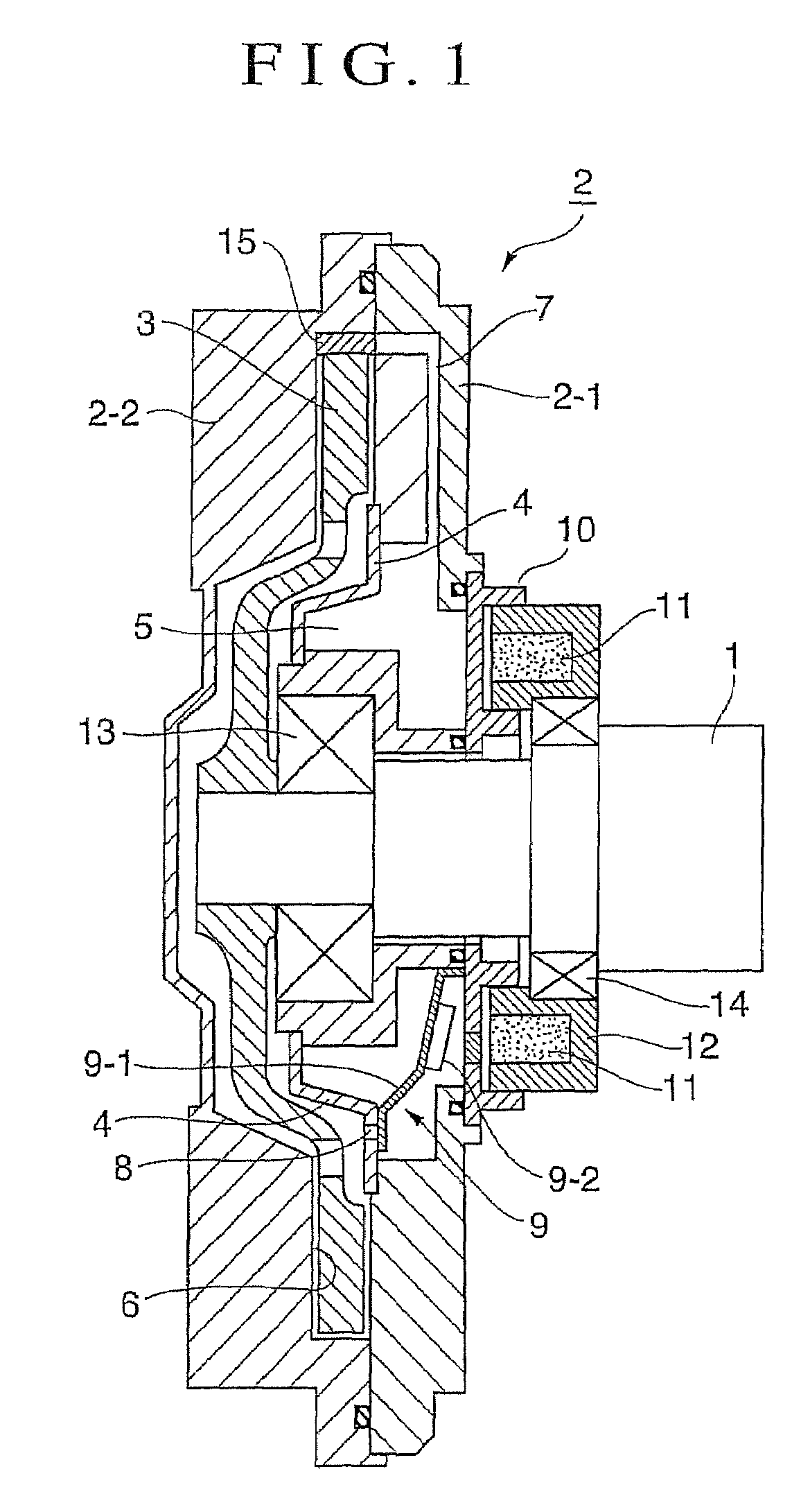
[0014]Specifically in the external control type fan clutch device shown in FIG. 1, a sealed casing 2 composed of a case 2-1 and a cover 2-2 is borne through a bearing 13 on a rotary shaft (or a drive shaft) 1 to be rotated by the drive of a drive unit (or an engine). This sealed casing 2 has its inside partitioned into an oil reservoir chamber 5 and a torque transmission chamber 6 by a partition 4 having an oil feed adjusting hole 8. In the torque transmission chamber 6, there is housed a drive disc 3, which is fixed at the leading end of the rotary shaft 1 thereby to form a torque transmission clearance between itself and the inner circumference of the torque transmission chamber.

[0015]Here, a dam 15 is formed in a portion of the inner circumference wall of the cover 2-2, as opposed to the outer circumference wall portion of the drive disc 3, at which the oil collects at the rotating time. The dam 15 has a function to pump the oil to an oil recovering circulation passage 7 formed i...


PUM


Abstract

A method is provided for controlling an external control type fan clutch. The method controls the On / Off of an electromagnet-activated valve for an oil feed adjusting hole. The method uses a PID control on the basis of radiator cooling liquid temperature, fan speed, transmission oil temperature, vehicle speed, engine speed, compressor pressure of an air conditioner, and an On / Off signal of the air conditioner. Individual gains of the PID control are determined by a gain matrix containing the optimum fan speed demanded by the engine, the actual metered fan speed, and the engine speed. The PID control is made on the basis of the gains to that a control signal is outputted. The control method can improve mileage, raise the cooling efficiency of an air conditioner and suppress fan noise.

Description

BACKGROUND OF THE INVENTION[0001]1. Field of the Invention[0002]The present invention relates generally to a control method for an external control type fan clutch of the type, in which the fan rotations for cooling an internal combustion engine of an automobile or the like are controlled according to a change in the ambient temperature or the rotation.[0003]2. Description of the Related Art[0004]In the prior art, there is an external control type fan clutch of this kind (as referred to JP-C-2911623, JP-A-2003-239741 and JP-A-9-119455). A sealed casing, which is composed of a nonmagnetic case borne through a bearing on a rotary shaft having a drive disc fixed at its leading end and a cover attached to the case, has its inside partitioned by a partition into an oil reservoir chamber and a torque transmission chamber having the drive disc fitted therein. The fan clutch is provided with a dam in a portion of the inner circumference wall of the cover opposed to the outer circumference w...

Claims


Application Information

Patent Timeline
Patent Type & Authority Patents(United States)
IPC IPC(8): B60K23/00
CPCF01P7/04F16D35/024F16D48/064F01P7/042Y10T477/71F01P2023/00F01P2025/60F01P2025/64F01P2025/66F02D41/083F16D2500/1026F16D2500/10418F16D2500/10468F16D2500/10487F16D2500/1107F16D2500/3056F16D2500/3067F16D2500/3068F16D2500/30803F16D2500/3108F16D2500/3109F16D2500/31446F16D2500/7027F16D2500/70424F16D2500/70626Y10T477/75F16D27/112
Inventor SHIOZAKI, KEN
Owner USUI KOKUSAI SANGYO KAISHA LTD
Why Eureka
Try Eureka