Portable solar energy system

a solar energy system and solar energy technology, applied in the field of electric power generation, can solve the problems that solar cell systems of this type are not without their own problems, and achieve the effects of preventing the discharging of the battery, optimizing the state of charge of the battery, and maximizing the useful life of the battery

Active Publication Date: 2008-06-17
GODMAN POWER GRP INC
View PDF31 Cites 210 Cited by
  • Summary
  • Abstract
  • Description
  • Claims
  • Application Information

AI Technical Summary

Benefits of technology

[0013]The system includes an energy storage and converting unit, which houses the battery and a dc-to-ac inverter. The inverter converts the stored energy of the battery, supplied at a low dc voltage, into ac voltage and current required for supplying conventional appliances. The current supplied to the battery is controlled by charge control circuitry, which prevents the discharge of energy from the battery into the cells of the solar panel and which manages the charging current supplied to the battery to optimize the state of charge of the battery and to maximize the useful life of the battery. The charge control circuitry may comprise a fuse and diode. The fuse limits the maximum current provided to the battery by the solar panel to prevent physical changes inside the battery that affect battery life and performance, while the diode prevents discharging of the battery through the cells of the solar panel when the solar panel is not receiving sufficient illumination to charge the battery.
[0014]Alternatively, the charge control circuitry can monitor the state of charge of the battery and control the charging current from the solar panel to maintain the battery at a fully charged state without overcharging the battery.

Problems solved by technology

This situation may occur in during building construction when electric power service has not been provided to a site.
However solar cell systems of this type are not without their own problems.

Method used


Image

  • Portable solar energy system
  • Portable solar energy system
  • Portable solar energy system

Examples


Embodiment Construction

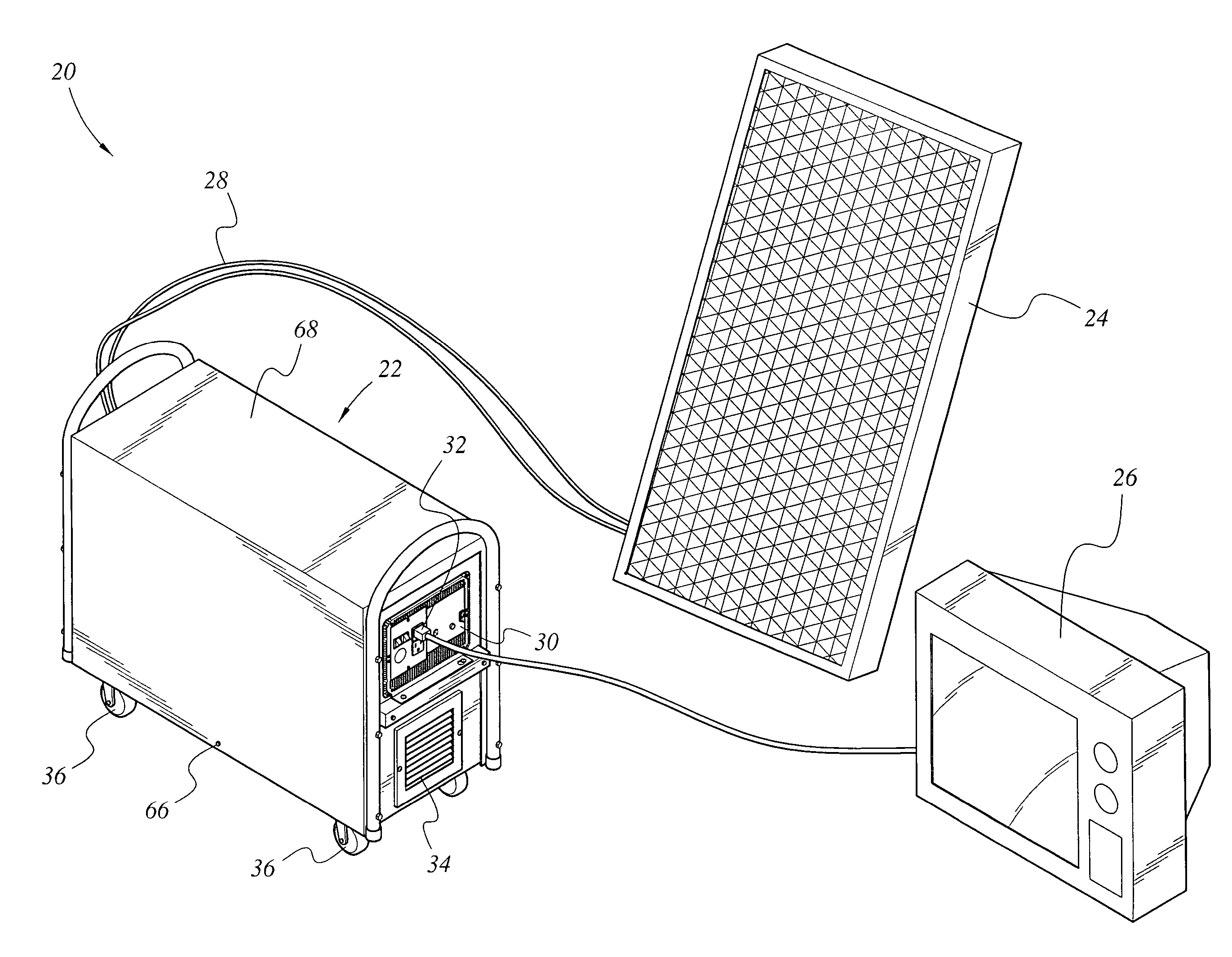
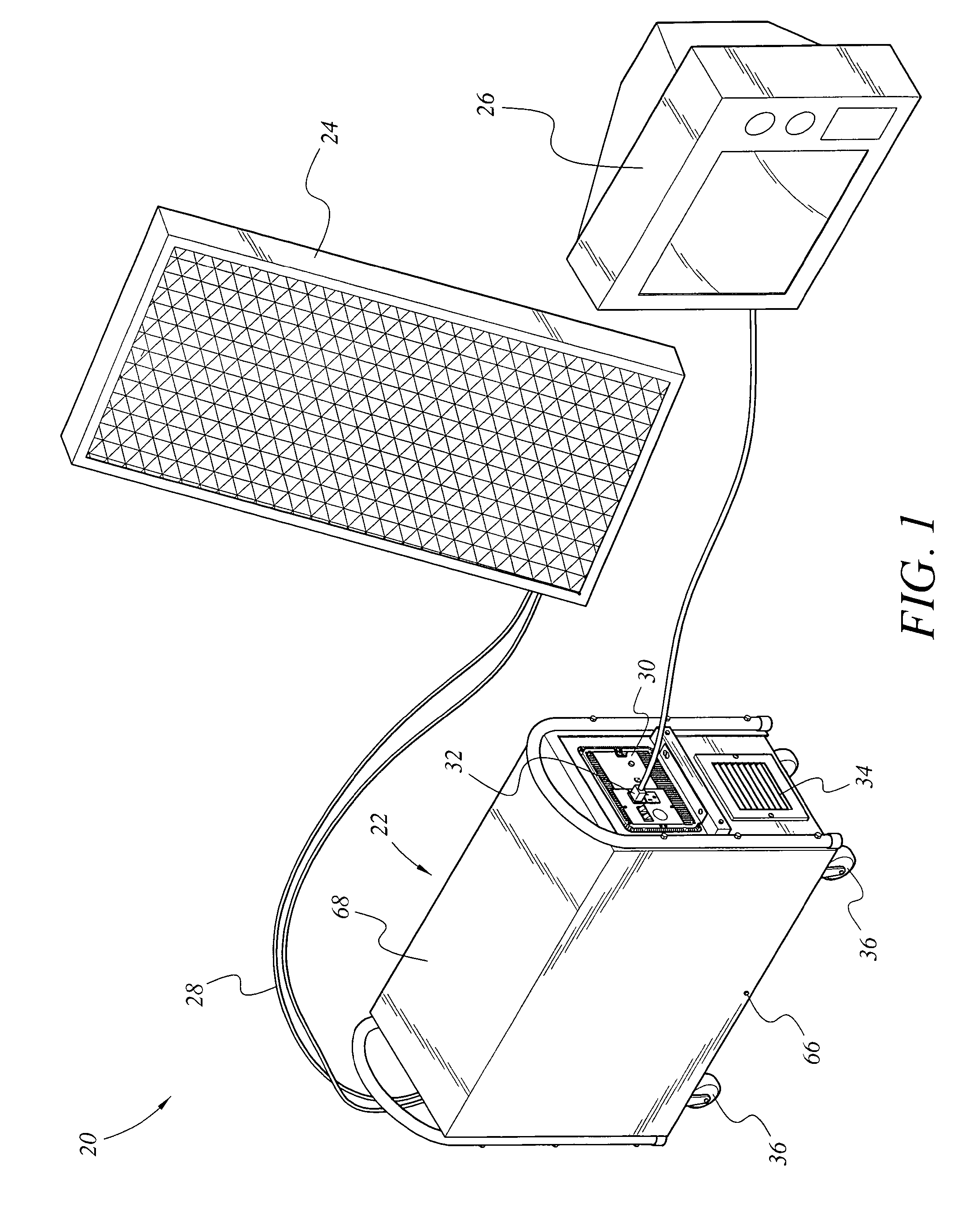
[0023]As shown in FIGS. 1, 2, and 3, the present invention is a portable solar power supply system 20 including a solar panel 24 and an energy storage and conversion unit 22. The system 20 provides power to an appliance 26, such as a television requiring 120-volt, 60 Hz, electric power.

[0024]The solar panel 24 comprises an array of solar cells mounted to a frame. Preferably the solar cells are photovoltaic cells, which convert sunlight directly into electrical power. The solar cells are connected in combinations to produce a solar panel 24 capable of generating the required voltage and current for charging a battery 52 located in the energy storage and conversion unit 22. The solar panel 24 is connected to the energy storage and conversion unit 22 through a two-conductor jacketed supply cord 28. The cord terminates in a connector 44 that releasably mates with a connector disposed on a panel of the housing of the energy storage and conversion unit 22.

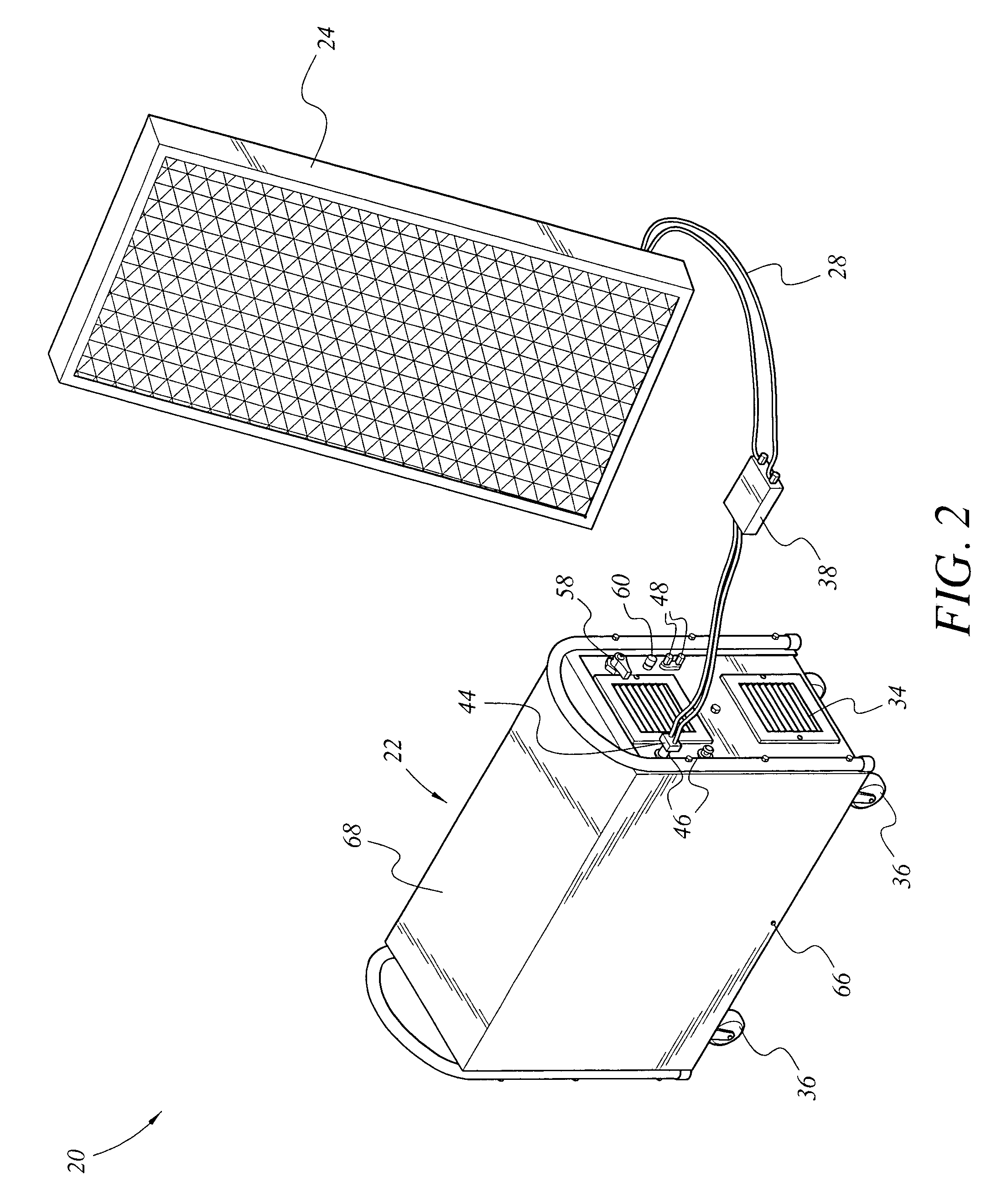
[0025]FIG. 2 shows the details of...


PUM

PropertyMeasurementUnit
frequencyaaaaaaaaaa
frequencyaaaaaaaaaa
voltageaaaaaaaaaa

Abstract

The portable solar energy system stores electrical energy generated by a solar panel, which is made of an array of photovoltaic cells, in a dc storage battery, and upon demand converts the dc voltage of the battery to an ac output suitable for supplying conventional electrical appliances. The battery is a sealed lead-acid type and may be an Absorbed Glass Mat (AGM) battery. The system includes an energy storage and converting unit, which houses the battery and a dc-to-ac inverter. The inverter converts the stored energy of the battery, supplied at a low dc voltage, into the ac voltage and current required for supplying conventional appliances. A charge controller manages the flow of current from the solar panel to optimize the state of charge of the battery and to maximize the useful life of the battery. Additional circuitry monitors the discharge level of the battery to limit deep discharging.

Description

BACKGROUND OF THE INVENTION[0001]1. Field of the Invention[0002]The present invention relates to electrical power generation, and in particular to a portable solar energy system for generating alternating current (ac) and direct current (dc) electrical power.[0003]2. Description of the Related Art[0004]It is frequently desired to provide electrical power to ac appliances through sources, which are independent of a national electric power grid.[0005]In some cases an alternate source of electrical power is desired because there is a need to use power in a place not currently serviced by the grid. This situation may occur in during building construction when electric power service has not been provided to a site. The situation may also occur in countries where the infrastructure for providing electrical power does not exist.[0006]It may also be desirable to provide an alternate source of electrical power in the aftermath of a disaster such as a storm, earthquake or other catastrophe ca...

Claims


Application Information

Patent Timeline
Patent Type & Authority Patents(United States)
IPC IPC(8): H01M10/44H01M10/46H02J7/00
CPCH02J7/0029H02J7/35H02J2007/004Y02B10/14Y02E10/566H02J7/00306Y02B10/10Y02E10/56
Inventor MATTICHAK, ALAN D.
Owner GODMAN POWER GRP INC
Why Eureka
Try Eureka