Conductive tamper switch for security devices

a technology of conductive tamper switches and security devices, applied in the field of switch mechanisms, can solve the problems of relative complexity of configuration and inability to lend, and achieve the effect of high efficiency and reliable operation and cost-effectiveness

Inactive Publication Date: 2008-06-17
HONEYWELL INT INC
View PDF18 Cites 981 Cited by
  • Summary
  • Abstract
  • Description
  • Claims
  • Application Information

AI Technical Summary

Benefits of technology

[0011]Accordingly, an advantage in the formation of a tamper switch installation in a wall or surface mounted keypad, which is highly efficient and reliable in operation while also concurrently being cost effective mounted, resides in the provision therein of a resilient rubber tamper switch, which possesses an electrically conductive end surface contacting a printed circuit board forming part of the operative system located within the keypad housing. The rubber tamper switch is normally in a compressed state upon the installation and mounting of the keypad on a surface or wall, in that in various embodiments of the invention, the tamper switch includes a rearwardly protruding portion, which is depressed upon the keypad being mounted on the wall or surface causing a constant contacting pressure to be exerted between the circuitry of the printed circuit board, which is fastened to the front cover of the keypad, and an electrically conductive end portion of the tamper switch during normal installation and operation of the keypad. Upon a tampering with the keypad by an unauthorized person, whereby the latter attempts to pull the front or cover portion of the keypad housing away from the back housing portion which is fastened to the wall or surface, this will cause the printed circuit board to be pulled forwardly, thereby enabling the compressed tamper switch, which is mounted to the interior of the housing back panel, to expand but lose contact of the conductive end thereof with the printed circuit board. The resultant short circuit or electrical malfunction will cause a signal to be generated and / or trigger an alarm at a remote monitoring installation or law enforcement agency, such as the police, indicative that a tampering action has been imparted to the keypad, and thereby alerting the appropriate authorities of that fact and to take protective steps.
[0014]In order to achieve the maximum displacement for the tamper switch mechanism, the latter of which is constituted of a resilient material, such as rubber, and preferably of silicon rubber, which is highly resistant to deleterious and corrosive conditions while maintaining its elasticity and formative integrity, and wherein the tamper switch mechanism includes a leading end forming an electrically conductive surface for contacting a printed circuit board in the keyboard, such as being of a conductive metal, for instance, such as a gold plated copper or the like, or a conductive rubber or plastic composition, while imparting a high degree of flexibility and compressibility to the tamper switch mechanism. This preferred silicon rubber material also provides a high degree of flexibility when mounting the keypad possessing a rearwardly protruding tamper mechanism on an uneven surface or wall, thereby avoiding tamper switch offsets and misalignments with the PCB during installation of the keypad. Furthermore, utilizing silicon rubber for the tamper switch exhibits excellent resistance to compression set at room temperature, high and low temperature stability and resistance to deleterious chemical and weather conditions. Through the invention, there is an important cost savings involved when replacing presently employed tamper switches and eliminating a mounting screw which is employed in the connection of the frangible segment portion of the back housing panel in order to enable the segment to be broken away when pulling the keypad from a surface on which it is mounted, by the action of an unauthorized person. Pursuant to the invention, the mounting screw and the frangible segment portion are eliminated by employment of the novel rubber tamper switch design, thereby saving time for installers by an error proof alignment of the keypad components.

Problems solved by technology

This is a relatively complex configuration, which does not readily lend itself to a simple tamper indicating switch mechanism which is incorporated in a wall or surface mounted keypad security device.

Method used


Image

  • Conductive tamper switch for security devices
  • Conductive tamper switch for security devices
  • Conductive tamper switch for security devices

Examples


Embodiment Construction

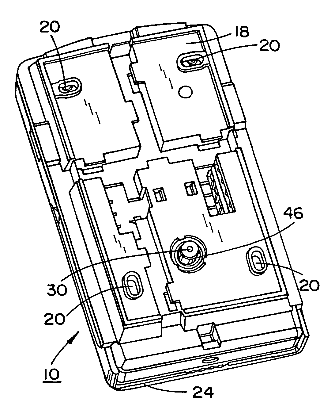
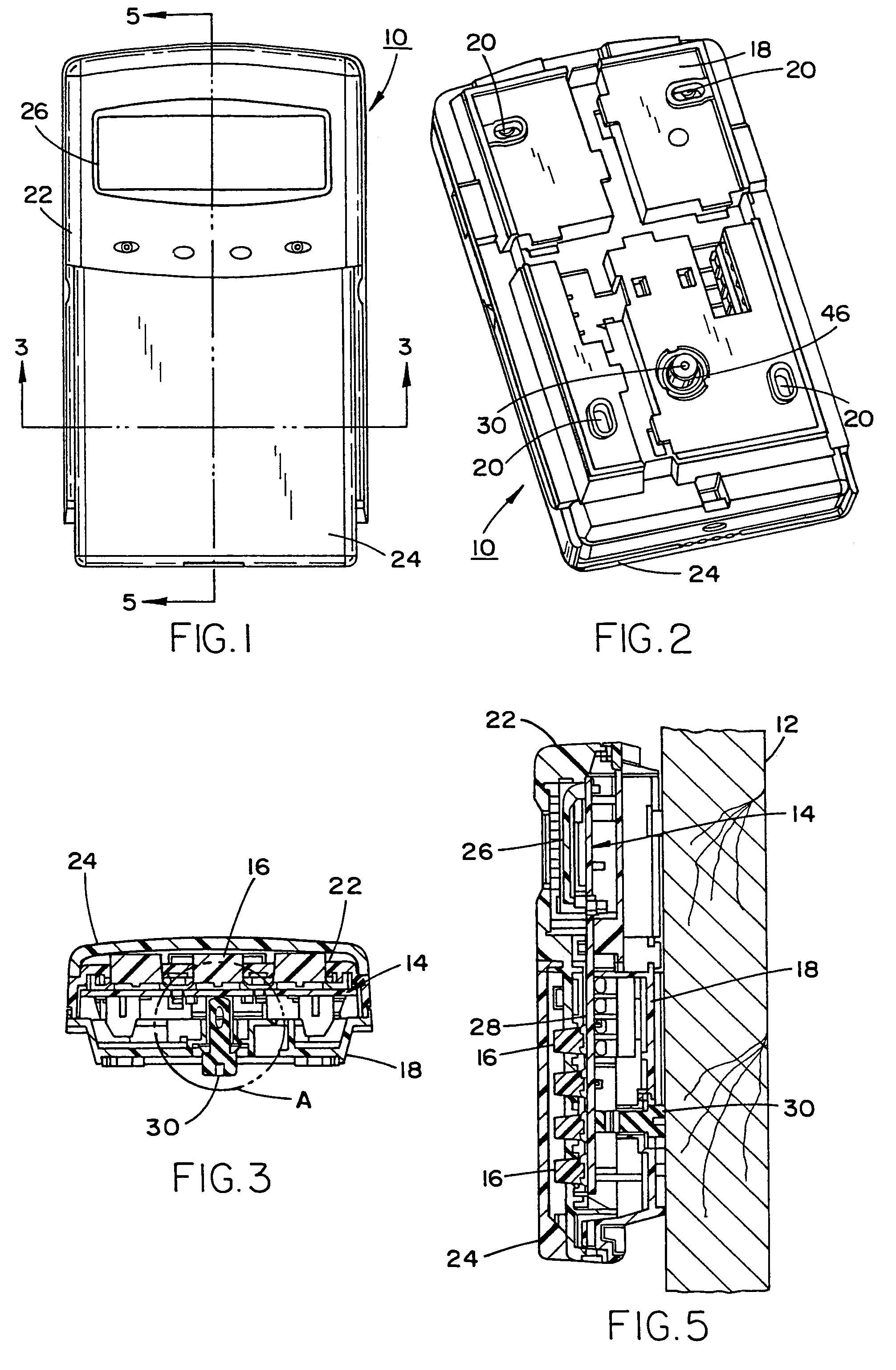
[0037]Referring now in specific detail to FIGS. 1 to 5 of the drawings, FIG. 1 illustrates a front view of a security interface device in the form of a keypad 10, which is adapted to be normally mounted on a vertical surface or wall 12, for example, as shown in FIG. 5 of the drawings. As illustrated, the keypad 10 contains the usual operating components including electronics and a printed circuit board 14 mounted therein. An array of touch keys 16 for imparting an operational activity code conjunction with a monitoring system (at a remote location), such as may be located at a burglar and fire alarm company or a law enforcement agency, for example, a local police station or precinct. The keys 16 may be activated by means of a touch control, or by means of a heat sensitive screen or panel, as is well known in the technology. The electronics and operating components housed within an essentially rectangular keypad housing, although other shapes are contemplateable, the latter of which ...


PUM


Abstract

A tamper switch mechanism utilized in security interface devices such as keypad installations to render them tamper-resistant, wherein the devices are generally connected to burglar alarm and fire alarm systems. More particularly, provided is a conductive tamper switch which is installed in a security interface device, such as a keypad, which upon an unauthorized attempt to dislodge the device or keypad from a wall or surface on which it is mounted, will trigger an alarm or generate a warning signal at a monitoring site indicative that an effort at tampering with the device has been effected. Also disclosed is a method of providing the tamper switch mechanism in a security interface device, such as a keypad installation.

Description

BACKGROUND OF THE INVENTION[0001]1. Field of the Invention[0002]The present invention relates to a switch mechanism utilized in security interface devices such as keypad installations to render them tamper-resistant, wherein the devices are generally connected to burglar alarm and fire alarm systems.[0003]More particularly, the present invention pertains to the provision of a conductive tamper switch which is installed in a security interface device, such as a keypad, which upon an unauthorized attempt to dislodge the device or keypad from a wall or surface on which it is mounted, will trigger an alarm or generate a warning signal at a monitoring site indicative that an effort at tampering with the device has been effected.[0004]Currently, security interface devices, such as those which consist of keypad units, are normally mounted on the walls or other upright surfaces of the most diverse locations, such as in homes, apartments, offices and manufacturing sites and plants. The secur...

Claims


Application Information

Patent Timeline
Patent Type & Authority Patents(United States)
IPC IPC(8): G08B1/08H04Q7/00
CPCG06F21/83G08B29/046
Inventor HSU
Owner HONEYWELL INT INC
Why Eureka
Try Eureka