Device for contact-free measurement of temperature

a technology of contact-free measurement and temperature, which is applied in the direction of thermometers, instruments, photometry, etc., to achieve the effect of simple means

Inactive Publication Date: 2008-06-24
OPTRIS
View PDF49 Cites 10 Cited by
  • Summary
  • Abstract
  • Description
  • Claims
  • Application Information

AI Technical Summary

Benefits of technology

[0008]The objective of the present invention is to develop and extend a device, of the generic type, for the contact-free measurement of temperature so that with simple means an economical and low-interference visualization of the position and / or the size of the measured spot on the measured object is made possible.
[0012]Alternatively to a capability of traversing or a capability of repositioning the detector along the optical canal a capability of switching between short-range focusing and long-range focusing by means of a special imaging optics can be achieved. For these capabilities the imaging optics comprises two lenses disposed one after another in the optical canal. Preferably both lenses are implemented in such a manner that they are identical, whereby the production costs can be reduced significantly. For switching from short-range focusing to long-range focusing a lens, preferably the lens facing the detector, can be implemented in such a manner that it can be repositioned along the optical canal, in particular traversed. In other words, the imaging optics is implemented in the sense of a vario objective so that the location of the detector with respect to the focal distance is changed via a change of the focal length of the imaging optics. In order to ensure a simple and reproducible repositioning of the lens it is possible, for example, to provide a snap and / or catch mechanism in the sense of a spring mimic.
[0018]Let it be noted that the measured spot at a distant position in principle could naturally also be marked by a larger or smaller number of lasers, thus, for example, by four or eight lasers. With the use of four lasers however, only an insufficient optical impression of a circle results while the use of eight lasers makes the measuring device more elaborate and expensive in its production without at the same time contributing to a significant improvement with regard to the clarity of the marking of the measured spot.
[0019]In regard to a simple mode of construction all the lasers could be disposed around the optical canal in such a manner that they are equidistant from one another. In regard to a comprehensible and clear marking of the measured spot however, disposing the six lasers for the visualization of the measured spot at a distant position around the optical canal in such a manner that they are equidistant from one another is to be preferred so that adjacent lasers are each at an angle of 60° with one another. The two lasers for marking the measured spot at a near position could then be disposed at any points between the lasers for marking the measured spot at a distant position, where they are positioned, with respect to the optical canal, opposite one another in an advantageous manner.
[0020]In regard to the capability of user-friendly operation and to most substantially avoiding incorrect adjustments on the user side, the device could be equipped in such a manner that the switching of the sighting device is done automatically as a function of the detector position. If the detector is located—e.g. for the measurement of the temperature of a small measured spot at a short distance—in the position which corresponds to the near position of the measured spot focus point, then the six lasers for long-range focusing could automatically become inactive, i.e. switched off. They would be automatically activated, i.e. switched on, as soon as the detector is in the other position, i.e. corresponding to the distant position of the measured spot focus point.
[0022]It is of quite particular advantage in this connection to choose the frequency of the laser drive to be proportional to the measured temperature. For example, the higher the measured temperature is, the faster the rotation could take place. Another possibility for the visualization of the results of the measurement consists of changing the color of the sighting rays as a function of the measured temperature. This could, for example, be achieved by mixing of green or red laser light, where the use of additional lasers of different colors would also be conceivable. Thus, on overshoot of a predefined threshold temperature, automatic switching from, for example, red lasers to green lasers could be provided.

Problems solved by technology

In addition to this, in case of a failure the device can also continue to be used, at least to a limited extent.

Method used


Image

  • Device for contact-free measurement of temperature
  • Device for contact-free measurement of temperature
  • Device for contact-free measurement of temperature

Examples


Embodiment Construction

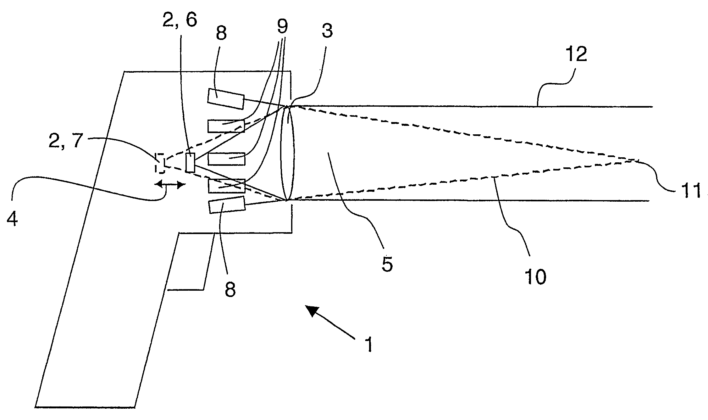
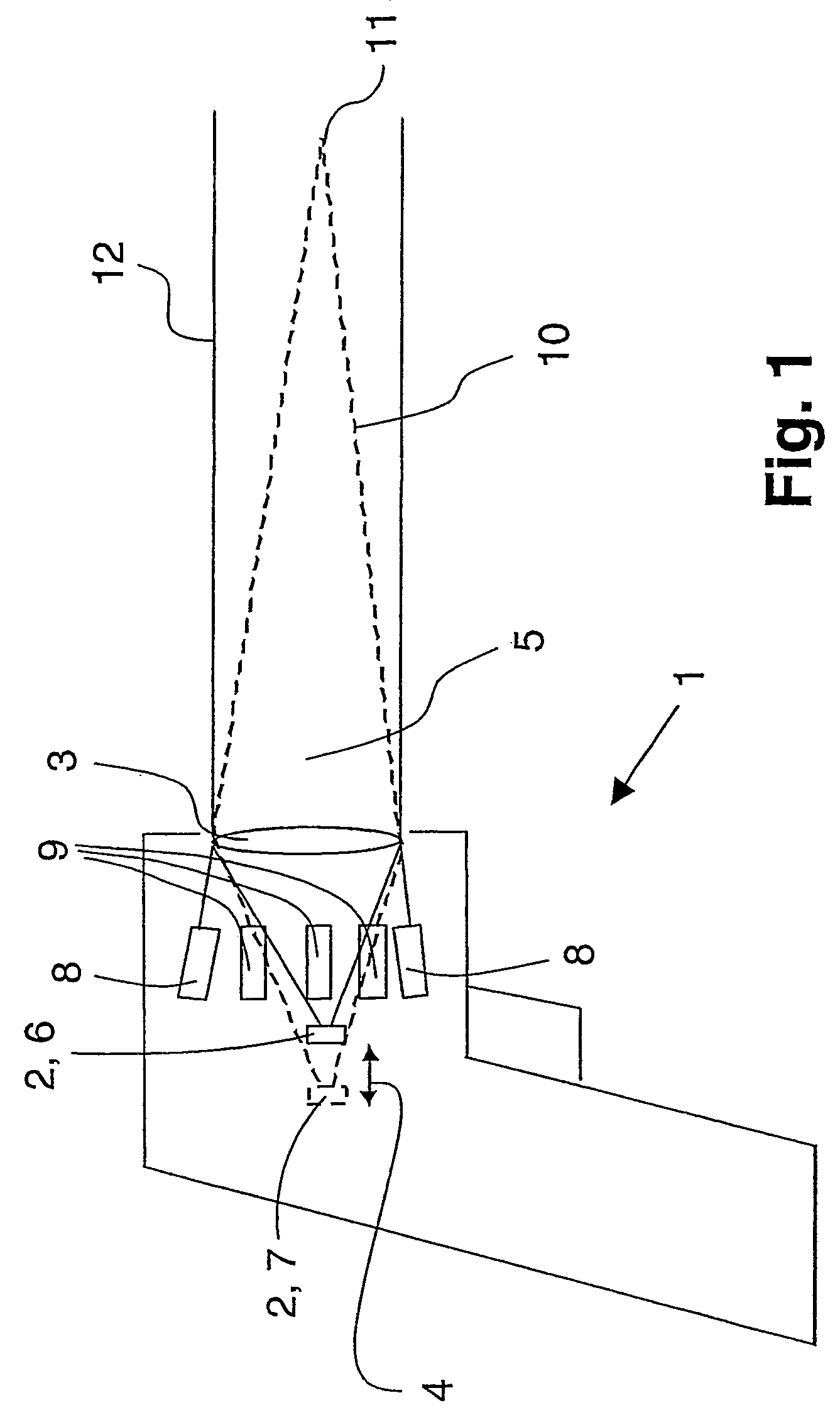
[0030]FIG. 1 shows in schematic side view a conceptual representation of a device according to the invention for contact-free temperature measurement in the form of a manual measuring device 1. Therein the measuring device 1 comprises an IR detector 2, onto which the thermal radiation emanating from an object (not represented) can be imaged by means of an optical system. In the embodiment example according to FIG. 1, the optical system is implemented as a simple convex lens 3 which focuses the thermal radiation onto the detector 2.

[0031]As indicated by the double arrow 4, the detector 2 is precisely and reproducibly traversable between two positions along the axis of an IR optical canal 5. In concrete terms, it is, in one case, the position 6, marked with solid lines, which corresponds to the distant position of the measured spot focus point. In this case the detector 2 is disposed at the focal point of the convex lens 3 and is consequently imaged at infinity by the convex lens 3. T...


PUM

PropertyMeasurementUnit
distanceaaaaaaaaaa
angleaaaaaaaaaa
diameteraaaaaaaaaa

Abstract

A device for measuring the temperature of a measured spot of a measured object without contacting the measured object is provided. The device includes a detector on which electromagnetic radiation emanating from the measured spot is projected by an optical imaging system. A sighting device for marking the position and / or the size of the measured spot includes at least two light sources. Each of the two light sources provides a respective sighting ray.

Description

CROSS-REFERENCE TO RELATED APPLICATIONS[0001]This application is a continuation of, and claims the benefit of priority to international PCT application number PCT / DE2004 / 001672, which was filed on Jul. 28, 2004, and which designates the United States. The disclosure of the referenced international PCT application is hereby incorporated herein by reference.FIELD OF THE INVENTION[0002]The invention relates to a device, for the contact-free measurement of temperature, with a detector onto which electromagnetic radiation emanating from a measured spot on a measured object can be imaged by means of imaging optics, and with a sighting device for marking the position and / or the size of the measured spot on the measured object, where the sighting device has a light source to provide at least two sighting beams.BACKGROUND OF THE INVENTION[0003]Devices for the contact-free measurement of temperature of the type under discussion have been known from practice for many years and are used to meas...

Claims


Application Information

Patent Timeline
Patent Type & Authority Patents(United States)
IPC IPC(8): G01J5/08G01K1/02
CPCG01J5/08G01J5/0806G01J5/084G01J5/0843G01J5/0859G01J5/089G01J5/0896G01J5/07
Inventor KIENITZ, ULRICH
Owner OPTRIS
Why Eureka
Try Eureka