[0008] The objective of the present invention is to develop and extend a device, of the generic type, for the contact-free measurement of temperature so that with simple means an economical and low-interference
visualization of the position and / or the size of the measured spot on the measured object is made possible.
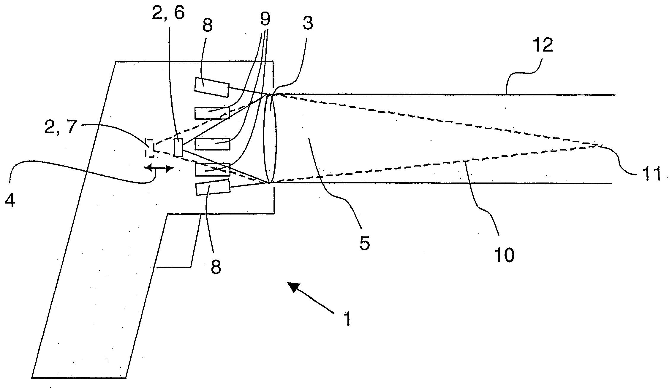
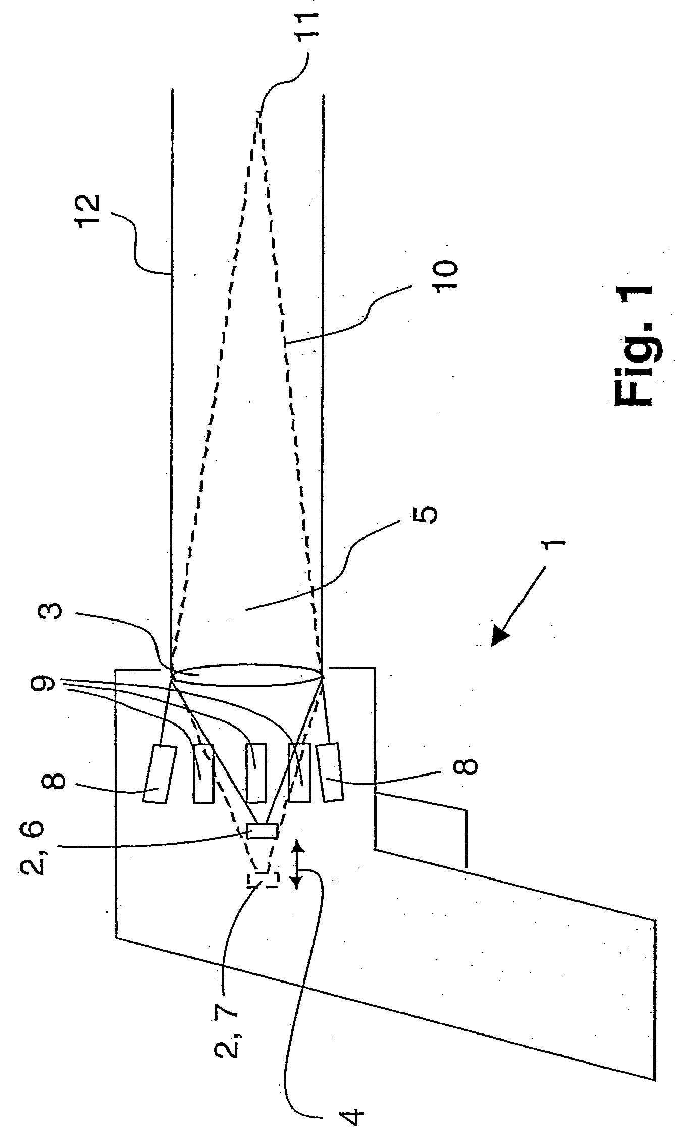
[0012] Alternatively to a capability of traversing or a capability of repositioning the
detector along the optical canal a capability of switching between short-range focusing and long-range focusing by means of a special imaging
optics can be achieved. For these capabilities the imaging
optics comprises two lenses disposed one after another in the optical canal. Preferably
both lenses are implemented in such a manner that they are identical, whereby the production costs can be reduced significantly. For switching from short-range focusing to long-range focusing a lens, preferably the lens facing the detector, can be implemented in such a manner that it can be repositioned along the optical canal, in particular traversed. In other words, the imaging optics is implemented in the sense of a vario objective so that the location of the detector with respect to the focal distance is changed via a change of the
focal length of the imaging optics. In order to ensure a simple and reproducible repositioning of the lens it is possible, for example, to provide a snap and / or catch mechanism in the sense of a spring mimic.
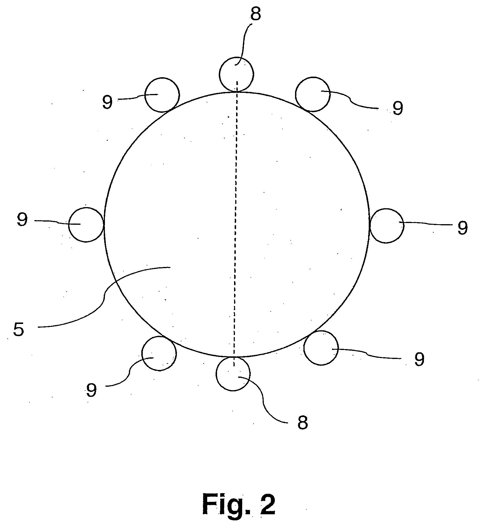
[0018] Let it be noted that the measured spot at a distant position in principle could naturally also be marked by a larger or smaller number of lasers, thus, for example, by four or eight lasers. With the use of four lasers however, only an insufficient optical impression of a circle results while the use of eight lasers makes the measuring device more elaborate and expensive in its production without at the same time contributing to a significant improvement with regard to the
clarity of the marking of the measured spot.
[0019] In regard to a
simple mode of construction all the lasers could be disposed around the optical canal in such a manner that they are
equidistant from one another. In regard to a comprehensible and clear marking of the measured spot however, disposing the six lasers for the
visualization of the measured spot at a distant position around the optical canal in such a manner that they are
equidistant from one another is to be preferred so that adjacent lasers are each at an angle of 60° with one another. The two lasers for marking the measured spot at a near position could then be disposed at any points between the lasers for marking the measured spot at a distant position, where they are positioned, with respect to the optical canal, opposite one another in an advantageous manner.
[0020] In regard to the capability of user-friendly operation and to most substantially avoiding incorrect adjustments on the user side, the device could be equipped in such a manner that the switching of the sighting device is done automatically as a function of the detector position. If the detector is located—e.g. for the measurement of the temperature of a small measured spot at a
short distance—in the position which corresponds to the near position of the measured spot focus point, then the six lasers for long-range focusing could automatically become inactive, i.e. switched off. They would be automatically activated, i.e. switched on, as soon as the detector is in the other position, i.e. corresponding to the distant position of the measured spot focus point.
[0022] It is of quite particular
advantage in this connection to choose the frequency of the
laser drive to be proportional to the measured temperature. For example, the higher the measured temperature is, the faster the rotation could take place. Another possibility for the
visualization of the results of the measurement consists of changing the color of the sighting rays as a function of the measured temperature. This could, for example, be achieved by mixing of green or
red laser light, where the use of additional lasers of different colors would also be conceivable. Thus, on overshoot of a predefined
threshold temperature, automatic switching from, for example, red lasers to green lasers could be provided.

