
Method and apparatus for generalized arc fault detection

a technology of generalized arc fault detection and arc fault detection, which is applied in the direction of testing circuits, emergency protective arrangements for limiting excess voltage/current, instruments, etc., can solve problems such as short circuits, fires in equipment, and arc faults in any electrical circui

Active Publication Date: 2008-06-24
HONEYWELL INT INC +1
View PDF10 Cites 41 Cited by
  • Summary
  • Abstract
  • Description
  • Claims
  • Application Information

AI Technical Summary

Problems solved by technology

Arc faults may occur in any of the electrical circuits, or along the wires.
If not detected promptly, arc faults may cause short circuits, malfunctions, and fires in the equipment serviced by the electrical circuits or wires exhibiting arc faults.
Arc fault detection and protection pose a significant challenge in such complex environments.
In contrast, series arc fault currents have low energy levels, being limited in magnitude by the electrical load along which they occur.
Hence, series arc faults are more difficult to detect.
Numerous serious or fatal electrical incidents are caused by low energy level arc fault conditions resulting from damaged or aging wire.
Such low energy level arc faults are not typically detected by conventional circuit breakers.
Aging wires are a source of arc faults.
The problem of aging wire systems extends to virtually all electrical systems in homes and other buildings, consumer products, nuclear power plants, public transit systems, and railroad systems.
Currently there are no systematic means to distinguish a series arc signal from normal and abnormal transient signals, or from various load profiles that occur in a typical AC or DC power distribution system.
Such methods are not universal, and are susceptible to frequent nuisance trips.
However, the nature of the distribution network environment and the characteristics of the loads in an electrical environment may not necessarily be known at the time when generalized libraries are created, such libraries being used to differentiate between arc faults and normal / abnormal transient characteristics of the loads.
This technique, however, does not detect arc faults with small absolute signatures.

Method used


Image

  • Method and apparatus for generalized arc fault detection
  • Method and apparatus for generalized arc fault detection
  • Method and apparatus for generalized arc fault detection

Examples


Embodiment Construction

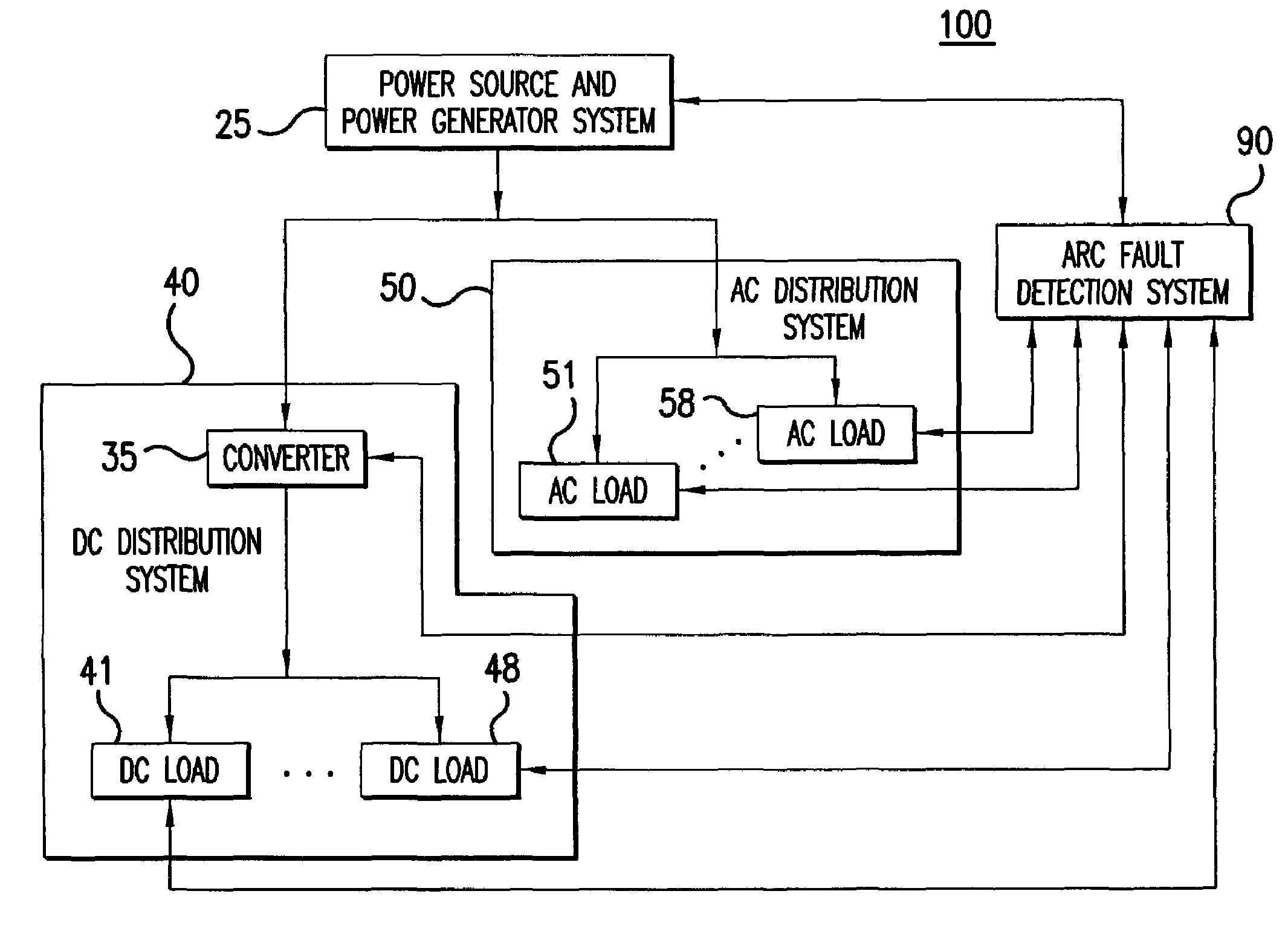
[0031]Aspects of the invention are more specifically set forth in the accompanying description with reference to the appended figures. FIG. 1 is a block diagram of an electrical system containing a generalized arc fault detection system according to an embodiment of the present invention. The electrical system 100 illustrated in FIG. 1 includes the following components: a power source and power generator system 25; a generalized arc fault detection system 90; a DC distribution system 40; and an AC distribution system 50. Operation of the electrical system 100 in FIG. 1 will become apparent from the following discussion.

[0032]Electrical system 100 may be associated with an aircraft, a ship, a laboratory facility, an industrial environment, a residential environment, etc. The power source and power generator system 25 transforms power and provides electrical energy in electrical system 100. The power source and power generator system 25 may include a generator of a vehicle, a turbine,...


PUM


Abstract

A method and an apparatus detect series and / or parallel arc faults in AC and DC systems. The method according to one embodiment inputs an AC current signal; extracts a fundamental component of the AC current signal and monitoring an amplitude variation profile for the fundamental component, thereby generating a first arc fault detection measure; detects non-stationary changes in the AC current signal applying at least one measure of order higher than one, thereby generating a second arc fault detection measure; and determines whether an arc fault exists based on the first arc fault detection measure and the second arc fault detection measure.

Description

CROSS REFERENCE TO RELATED APPLICATION[0001]The present application claims priority under 35 U.S.C. §119(e) of U.S. Provisional Application No. 60 / 660,336 filed Mar. 11, 2005, the entire contents of which are herein incorporated by reference in their entirety.BACKGROUND OF THE INVENTION[0002]1. Field of the Invention[0003]The present invention relates to electric power distribution systems, and more particularly to a method and apparatus for detecting series and / or parallel arc faults for electric power systems.[0004]2. Description of the Related Art[0005]Electrical systems used in complex environments such as aerospace systems, industrial environments, vehicles, and residential environments include a large number of electrical circuits, devices, and wires. Arc faults may occur in any of the electrical circuits, or along the wires. If not detected promptly, arc faults may cause short circuits, malfunctions, and fires in the equipment serviced by the electrical circuits or wires exhi...

Claims


Application Information

Patent Timeline
Patent Type & Authority Patents(United States)
IPC IPC(8): G01R31/08
CPCH02H1/0015H02H1/0092G01R31/008G01R31/1227G01R31/14
Inventor KOJORI, HASSAN ALILI, CHUNLINDAWSON, FRANCIS P. J.
Owner HONEYWELL INT INC
Learn More