Power module driving control apparatus and hybrid vehicle

a technology of driving control apparatus and power module, which is applied in the direction of hybrid vehicles, cycles, transportation and packaging, etc., can solve the problem of insufficient starting acceleration performance and achieve the effect of sufficient accelerator respons

Inactive Publication Date: 2008-07-01
HONDA MOTOR CO LTD
View PDF6 Cites 23 Cited by
  • Summary
  • Abstract
  • Description
  • Claims
  • Application Information

AI Technical Summary

Benefits of technology

[0012]According to the first embodiment of the present invention, if an acceleration request is made through an accelerator operation performed by a rider when the rotational speed on the input side of the clutch falls short of the set value, the control means sends a control signal to the motor generator so that the rotational speed on the input side of the clutch becomes close to the set value. This increases the speed of the crankshaft on the input side of the clutch so that the clutch may be quickly connected and the power drive of the engine may be transmitted to the driving wheel side.
[0022]According to the fifth embodiment of the present invention, a sufficient acceleration response can be achieved at all times despite adoption of the speed sensing type clutch. It is also possible to quickly switch from the drive by the electric motor to the drive by the engine.

Problems solved by technology

It can therefore happen that it takes time to switch from a motor drive to an engine drive and thus only insufficient starting acceleration performance can be derived.

Method used


Image

  • Power module driving control apparatus and hybrid vehicle
  • Power module driving control apparatus and hybrid vehicle
  • Power module driving control apparatus and hybrid vehicle

Examples


Embodiment Construction

[0031]A preferred embodiment of the present invention will be described with reference to the accompanying drawings.

[0032]In the description that follows hereunder, “front side” refers to a forward direction of a vehicle. “Right-hand side” and “left-hand side” refer to the right-hand side and the left-hand side of the vehicle, looking the vehicle in the forward direction.

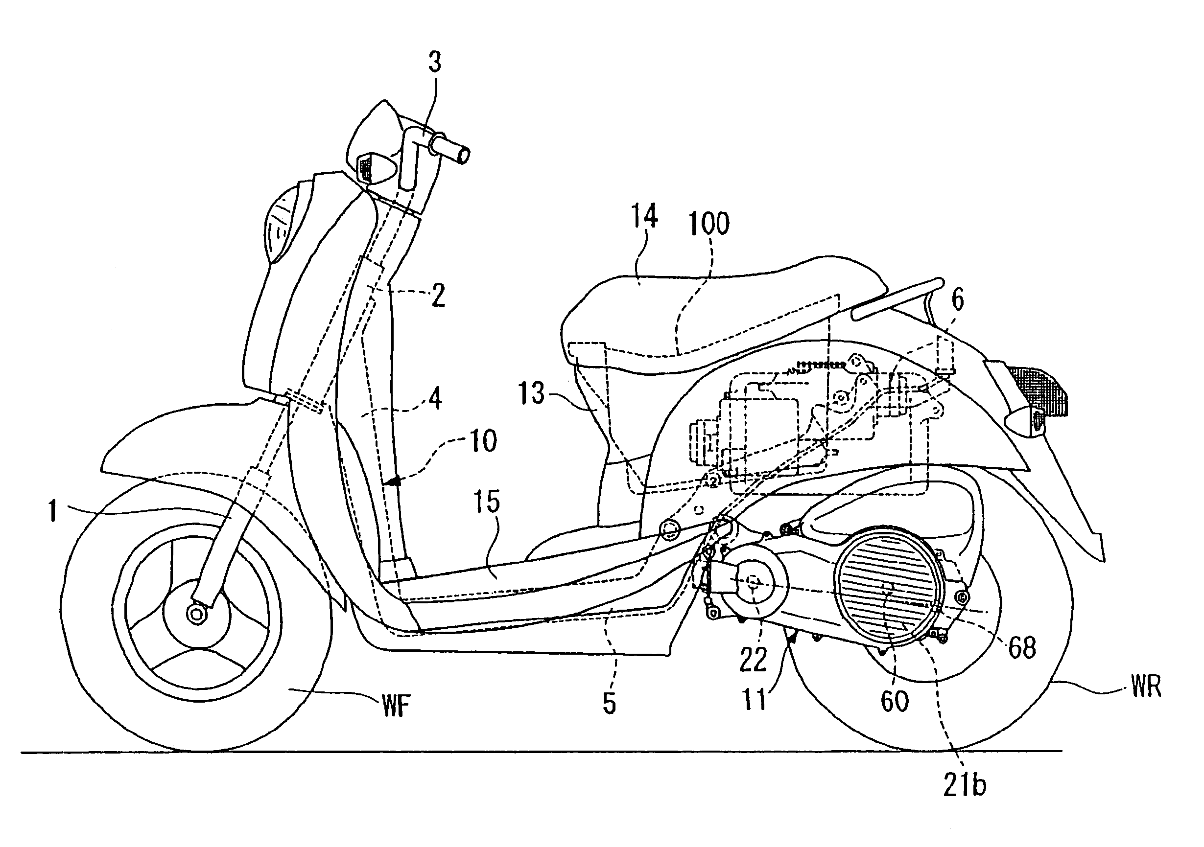
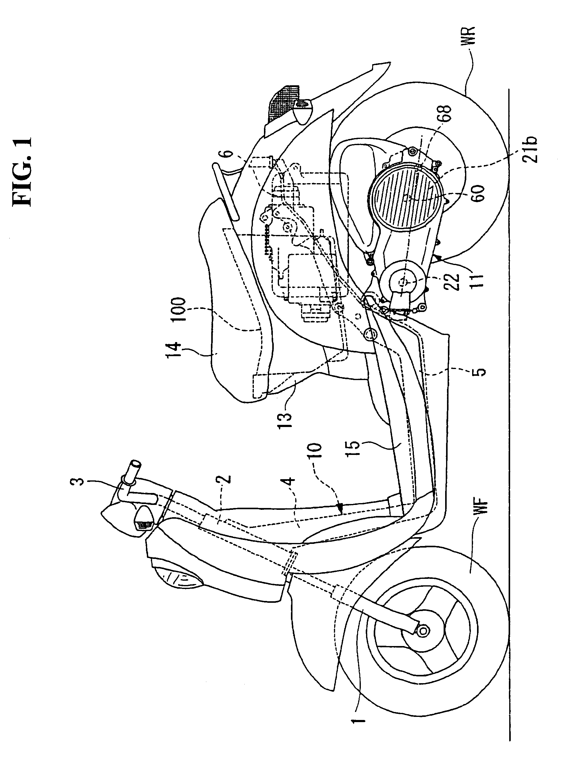
[0033]The vehicle according to the preferred embodiment of the present invention is a scooter type hybrid vehicle. Referring to FIG. 1, the vehicle includes a power unit 11 including an electric motor 21b. The power unit 11 is swingably supported as a unit swing type on a vehicle body frame 10 together with a rear wheel WR.

[0034]A front fork 1 for journaling a front wheel WF is disposed forward of the vehicle. The front fork 1 is rotatably supported on a head pipe 2 that forms part of the vehicle body frame 10. An upper end portion of the front fork 1 is connected to a handlebar 3. The vehicle can be steered by oper...


PUM


Abstract

To provide a power module driving control apparatus and a hybrid vehicle capable of obtaining sufficient accelerator response despite adoption of a speed sensing type clutch for connection and disconnection of a power drive between an engine side and a driving wheel side. When a rotational speed on an input side of a centrifugal clutch falls short of a set value, at which the clutch can be connected, and an acceleration request is made by a rider, a control unit controls a motor generator so as to bring the rotational speed on the input side of the clutch near to the set value. When the motor generator is made to function as a motor, rotation on the input side of the clutch is assisted. When the motor generator functions as a generator, an amount of electricity generated is decreased.

Description

CROSS-REFERENCE TO RELATED APPLICATIONS[0001]The present non-provisional application claims priority under 35 USC 119 to Japanese Patent Application No. 2004-233156 filed on Aug. 10, 2004 the entire contents thereof is hereby incorporated by reference.BACKGROUND OF THE INVENTION[0002]1. Field of the Invention[0003]The present invention relates to a driving control apparatus, in which a motor generator connected to a crankshaft of an engine is controllable. A power module is provided for transmitting an engine power drive to the side of a driving wheel through a clutch. A hybrid vehicle is provided with the driving control apparatus.[0004]2. Description of Background Art[0005]A hybrid vehicle mounted with an engine and an electric motor as a vehicle power drive sources is known. See, for example, Japanese Patent Laid-open No. 2000-350310.[0006]In the hybrid vehicle disclosed in Japanese Patent Laid-open No. 2000-350310, the electric motor is operated with a torque value greater than ...

Claims


Application Information

Patent Timeline
Patent Type & Authority Patents(United States)
IPC IPC(8): B62K11/00B60K6/442B60L50/16B60K6/48B60K6/543B60K17/04B60L15/00B60W10/02B60W10/08B60W20/00F16D43/14
CPCB60K6/44B60L11/14B60W10/08B62M7/12B60K6/543Y10S903/914B60L2200/12B60L2240/421B60L2240/525B60W20/00B60W2510/0208B60W2540/10B60W2710/081B60Y2200/12B62K2202/00Y02T10/623Y02T10/642Y02T10/7077Y02T10/70B60L50/16Y02T10/62Y02T10/64Y02T10/7072B60K6/22B62M23/02B60W20/40B60W10/02
Inventor KOJIMA, HIROYUKIOZEKI, TAKASHITSUKADA, YOSHIAKIUCHISASAI, HIROAKI
Owner HONDA MOTOR CO LTD
Why Eureka
Try Eureka