
Apparatus and method for electrostatically depositing aerosol particles

a technology of aerosol particles and apparatus, applied in electrostatic separation, chemistry apparatus and processes, coatings, etc., can solve the problems of difficult production of particles in this nanometer size range and depositing on substrates, and achieve the effect of high aerosol flow and effective use of electric fields

Active Publication Date: 2008-07-01
CORNING INC
View PDF33 Cites 37 Cited by
  • Summary
  • Abstract
  • Description
  • Claims
  • Application Information

AI Technical Summary

Benefits of technology

[0015]The apparatus for ESD and ESD methods of the present invention as described herein, address the above-mentioned disadvantages of the conventional ESD methods, in p

Problems solved by technology

However, particles in this nanometer size range are difficult to produce and deposit onto a substrate.
Another challenge of depositing aerosol particles onto a substrate is overcoming the velocity of the flow of the aerosol from the particle generator such that the electric field used in ESD can overcome the velocity of the flow of the aerosol and the aerosol particles are deposited onto the substrate.

Method used


Image

  • Apparatus and method for electrostatically depositing aerosol particles
  • Apparatus and method for electrostatically depositing aerosol particles
  • Apparatus and method for electrostatically depositing aerosol particles

Examples


example

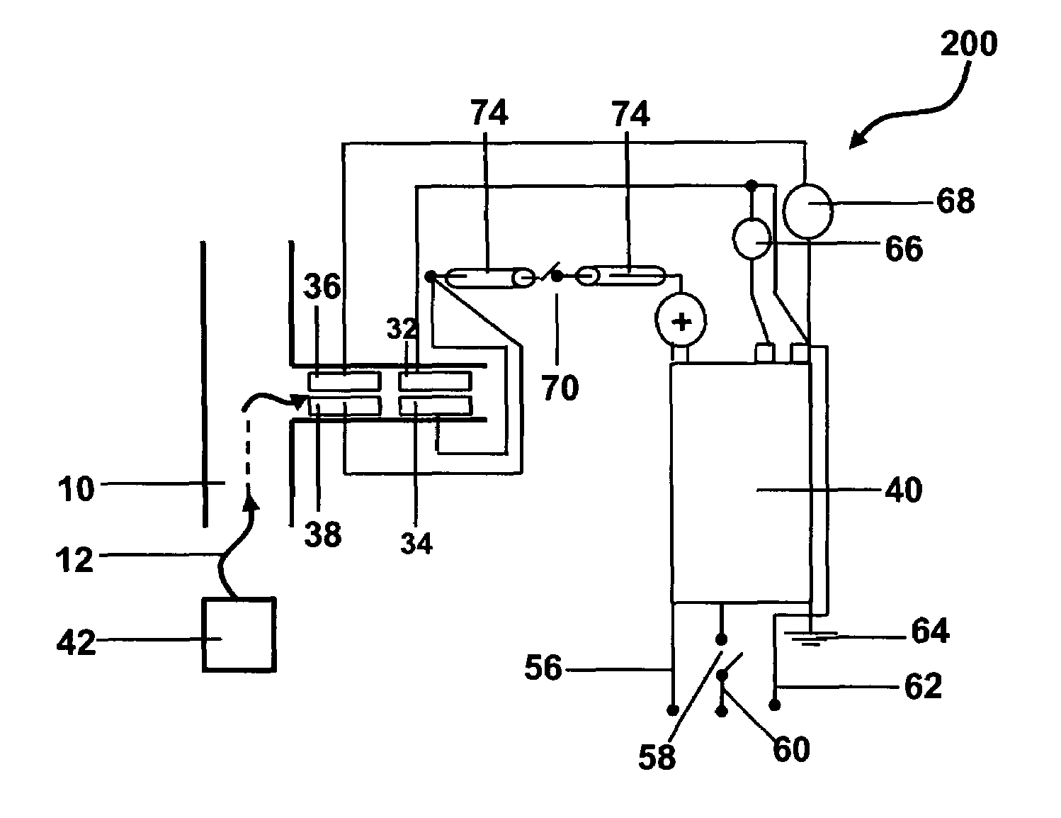
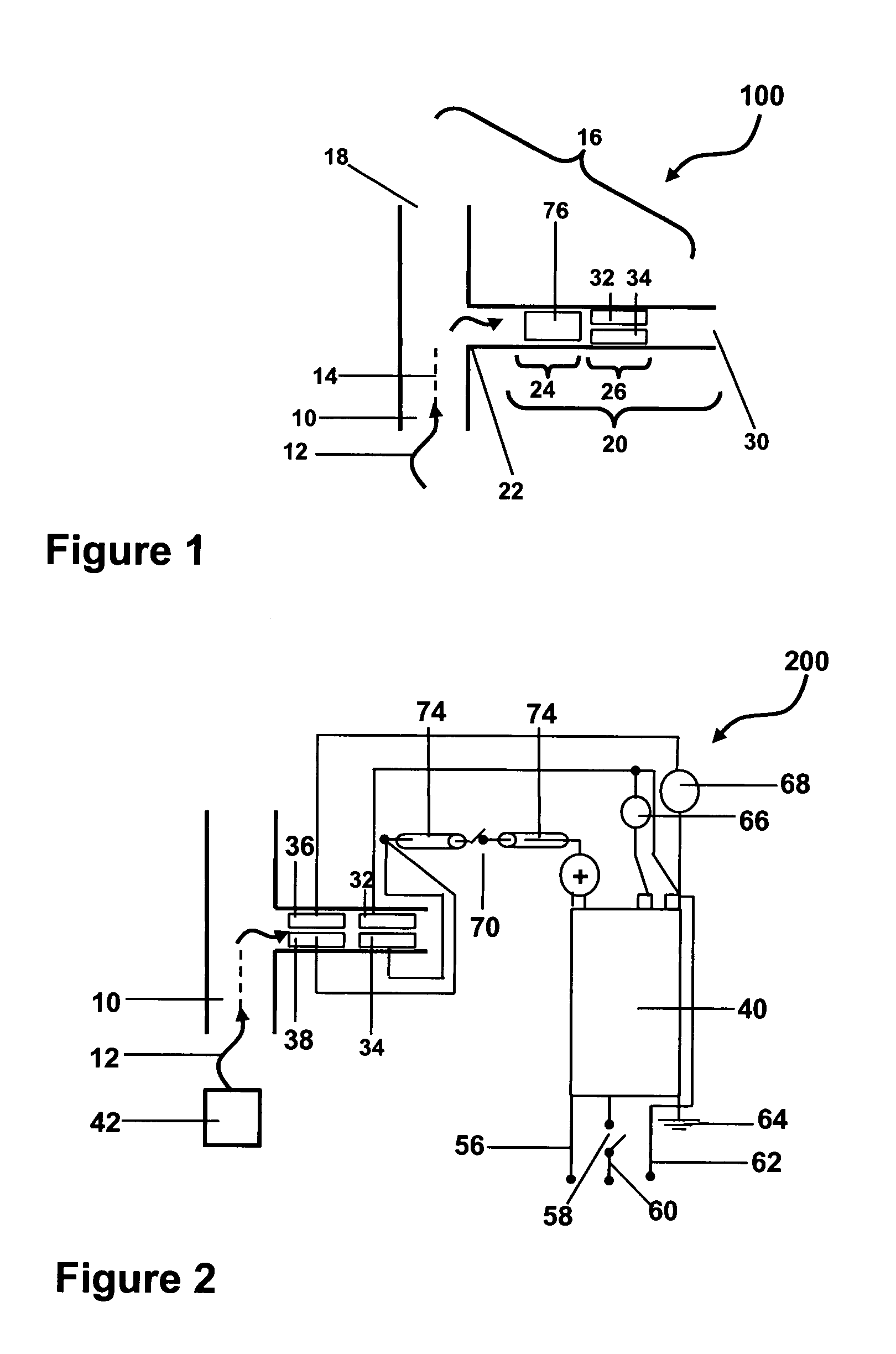
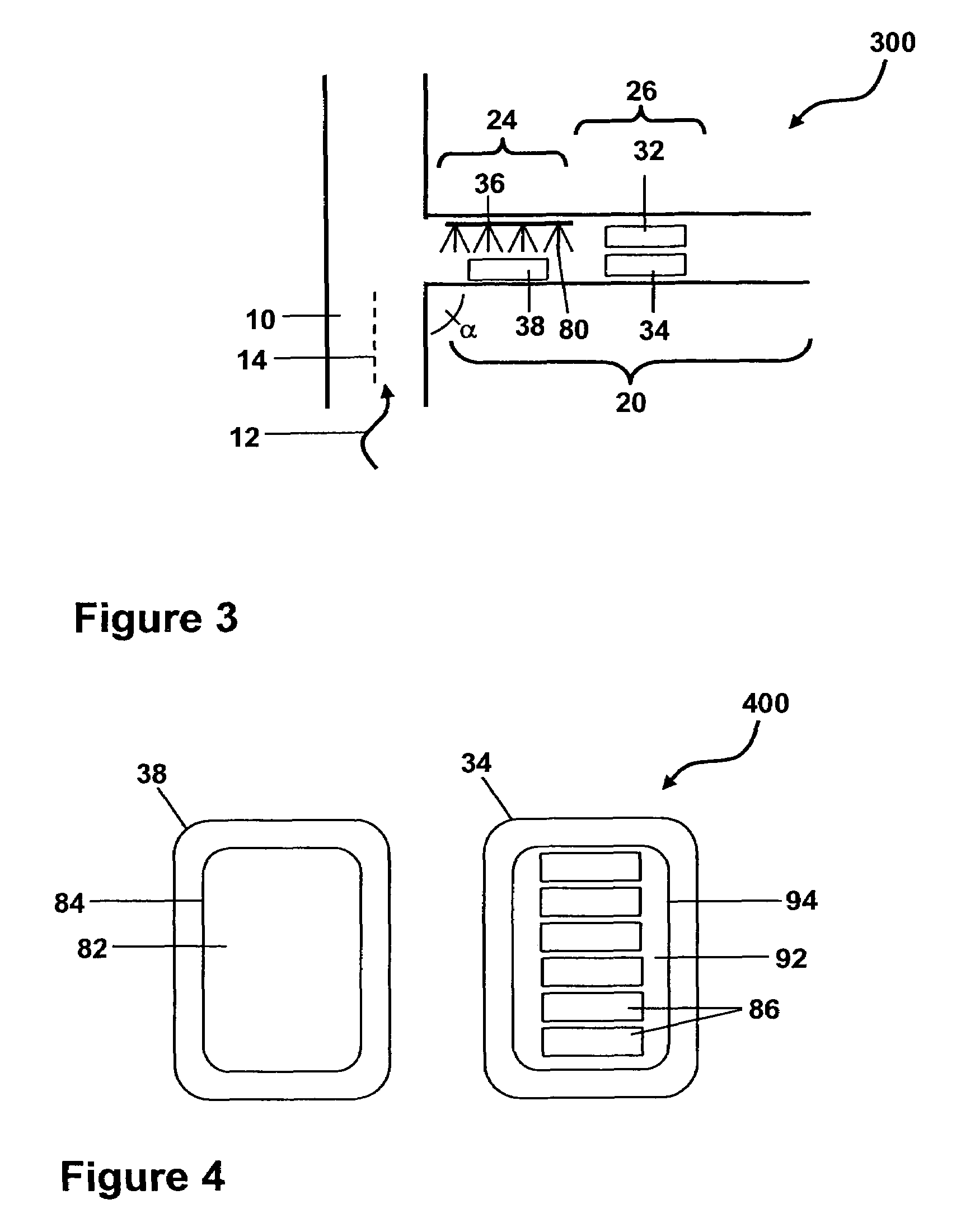
[0061]A flame spray pyrolysis (FSP) particle generator was used to generate a flow of aerosol, flammable alkoxide based solutions were pumped to an external mixing gas-assisted atomizer (Schlick Model 970 / 4-S3) by a 1 Liter capacity precision piston pump (Isco, Inc. Model 1000D). The resulting spray formed a self-sustaining flame when passed through a ring of twelve CH4 / O2 pilot flames. The flow of aerosol carrying nanoparticles produced in the FSP particle generator passed through a corona discharge section (a set of corona brushes and an oppositely charged planar electrode) slightly above the flame for ionic electrostatic charging. Then, the flow of aerosol (carrier gas with charged particles) cooled down in the vertical part of the generator (about 1.2 meters above the burner face) and reached the deposition unit consisting of a central electrode and target substrates made of Corning 1737™ glass. A quartz tube with 0.14 m internal diameter and 1.5 meters in length covered all par...


PUM

PropertyMeasurementUnit
Angleaaaaaaaaaa
Angleaaaaaaaaaa
Lengthaaaaaaaaaa

Abstract

An apparatus useful for electrostatic deposition (ESD) of aerosol particles and methods of depositing the aerosol particles onto a substrate are disclosed. The ESD apparatus and the method of the present invention are useful for electrostatically depositing nanoparticles produced by gas-phase synthesis onto a substrate where the velocity of the flow of aerosol can be controlled.

Description

BACKGROUND[0001]1. Field of the Invention[0002]The present invention relates generally to electrostatic deposition (ESD) of aerosol particles and more particularly to an apparatus useful for ESD and methods of depositing the aerosol particles onto a substrate.[0003]2. Technical Background[0004]Over the years, there has been rapid progress in the areas of electronics, materials science, and nanoscale technologies resulting in, for example, smaller devices in electronics, advances in fiber manufacturing and new applications in the biotechnology field. The ability to generate and collect increasingly smaller, cleaner and more uniform particles is necessary in order to foster technological advances in areas which utilize small particulate matter. The development of new, efficient and adaptable ways of producing small particulate matter and subsequently collecting or depositing the small particulate matter onto a substrate becomes more and more advantageous.[0005]The size of a particle o...

Claims


Application Information

Patent Timeline
IPC IPC(8): B03C3/40
CPCB03C3/383C03C17/06C23C26/00C23C24/04C03C2217/251C03C2217/27C03C2218/115C03C2217/268
Inventor COFFEY, CALVIN THOMASFEKETY, CURTIS ROBERTFILIPPOV, ANDREY VOSTERHOUT, CLINTON DAMONSALA, MARTIN ANDREWTRUESDALE, CARLTON MAURICE
Owner CORNING INC
Features
  • Generate Ideas
  • Intellectual Property
  • Life Sciences
  • Materials
  • Tech Scout
  • Unparalleled Data Quality
  • Higher Quality Content
  • 60% Fewer Hallucinations
Learn More