System for maintaining pH and sanitizing agent levels of water in a water feature

a water feature and water level technology, applied in the direction of gymnasium, ratio control, liquid separation auxiliary apparatus, etc., can solve the problems of high cost, difficult and expensive operation of water features (e.g., spas or swimming pools), and users' significant difficulty in adjusting the ph level using highly concentrated ph-modifying materials

Active Publication Date: 2008-07-01
HALOGEN SYST INC
View PDF31 Cites 28 Cited by
  • Summary
  • Abstract
  • Description
  • Claims
  • Application Information

AI Technical Summary

Problems solved by technology

Balancing the water chemistry (e.g., pH levels and sanitizing agent levels) in water features (e.g., spas or swimming pools) can be a challenging and expensive operation.
In particular, “balancing the water” in a spa can be much more challenging than in a pool due to the relatively small volume of water in spas.
Because of the relatively small volume of water in spas, users have significant difficulty in adjusting the pH level using highly concentrated pH-modifying materials, such as acidic materials (e.g., sodium bisulfate) or alkaline materials (e.g., sodium carbonate).
The persistence of low or high pH levels can cause or contribute to corrosion of metal components of the heater and to scaling of the heater.
In addition, because sanitizing agents such as chlorine are less efficient at high pH levels, improper pH levels can lead to unsanitary conditions.
Control of the sanitizing agent (e.g., chlorine or bromine) to ensure that a spa is sanitary is similarly difficult and expensive.
Variations of the frequency of use of the water feature by bathers or other system parameters can render such devices useless and can require supplemental addition of sanitizing agents to the water.
However, an overfeed condition in which too much sanitizing agent is used can result in corrosion of metal components of the water feature in general, and in the heater in particular.
This repeated addition of chemicals to the water of the water feature in an attempt to control the pH level and the sanitizing agent level is sometimes referred to as “chemical warfare.” Some frustrated consumers often end up draining their spas and starting over with fresh water rather than spending the time and effort to “balance the water.” Other frustrated consumers simply ignore the pH level of the water altogether, which can result in unsanitary conditions due to the reduced efficacy of the sanitizing agent.
Such systems have the disadvantage of feeding concentrated chlorine at a low pH level directly into the circulation system ahead of the heater, pump, and filter, potentially causing corrosion of these components.
Such systems are prone to clogging of the injector orifices.
Such systems can not be installed below the water level of the water feature due to backflow.
Concentrated chlorine enters the water pump and water heater in this arrangement and can damage various equipment of the water feature.
Additionally, failure of the float system can cause loss of pool water.
Automatic control of the pH level of a water feature is further complicated by periodic recalibration of the pH controller.
This reference material is depleted through migration through the porous junction, resulting in changes of the reference potential.
This procedure can be quite difficult for a user.
In addition, the location of the pH sensor can make it difficult to access.
The recalibration process is typically performed monthly, or even weekly in some cases, and can require more effort than simply testing and adding chemicals.

Method used


Image

  • System for maintaining pH and sanitizing agent levels of water in a water feature
  • System for maintaining pH and sanitizing agent levels of water in a water feature
  • System for maintaining pH and sanitizing agent levels of water in a water feature

Examples


Embodiment Construction

System Overview

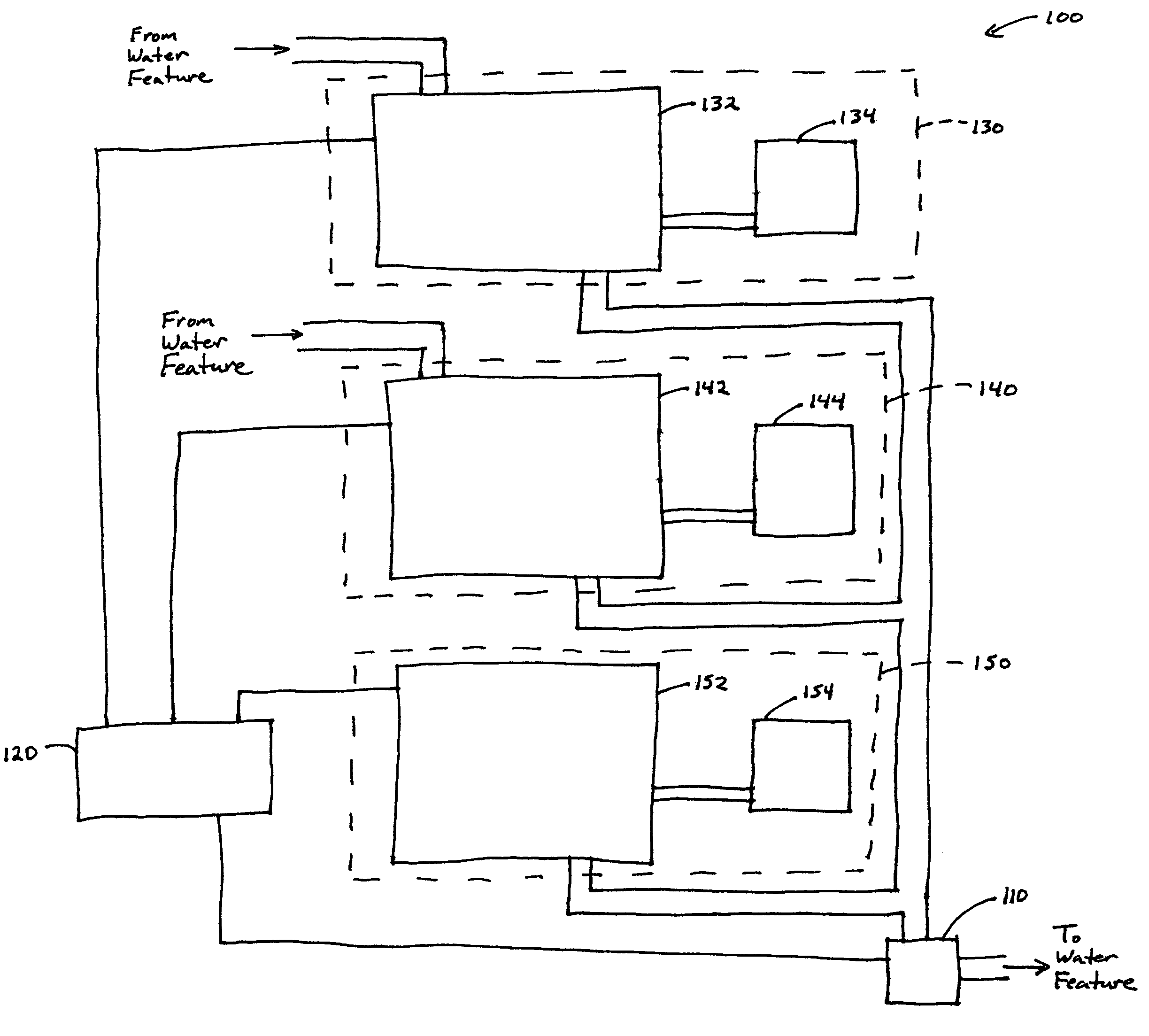
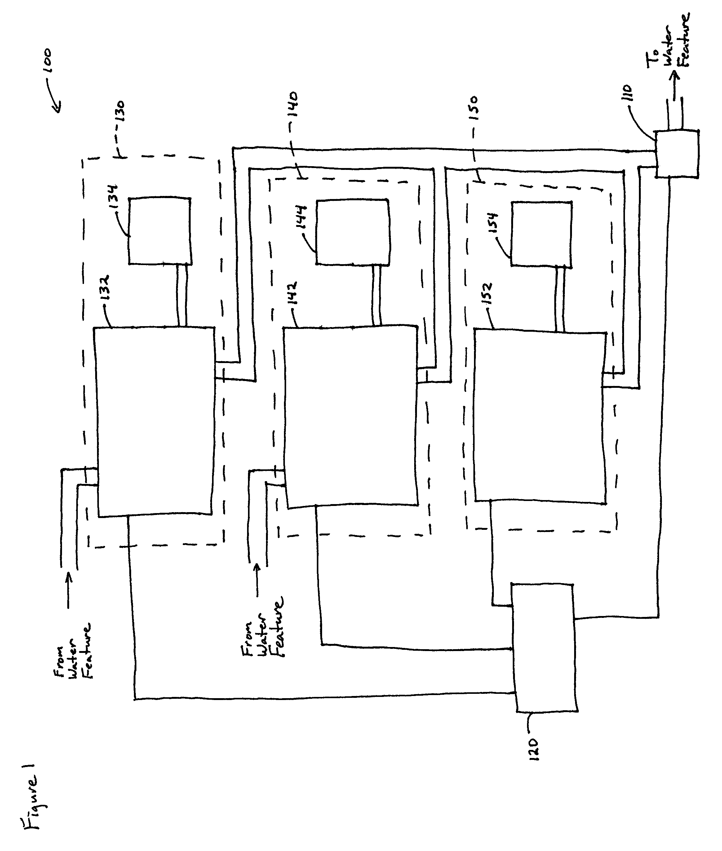
[0057]FIG. 1 schematically illustrates an exemplary system 100 fluidly coupled to a water feature (e.g., spa, Jacuzzi, jetted tub, whirlpool bath, or swimming pool) for automatically maintaining at least one of a pH level and a sanitizing agent level of water in the water feature. As used herein, the term “fluidly coupled” describes configurations having a fluid pathway for direct fluid flow from a first component to a second component, and configurations having a fluid pathway for indirect fluid flow from one component to another (e.g., fluid flow through one or more additional components to flow from the first component to the second component).

[0058]The system 100 comprises a sensor assembly 110 fluidly coupled to the water feature. The sensor assembly 110 is responsive to at least one of a pH level of the water and a sanitizing agent level of the water. The sensor assembly 110 is responsive to the pH level by generating a pH signal corresponding to the pH level. T...


PUM

PropertyMeasurementUnit
pHaaaaaaaaaa
flow rateaaaaaaaaaa
pressureaaaaaaaaaa

Abstract

A system automatically maintains at least one of a pH level and a sanitizing agent level of water in a water feature. The system includes a sensor assembly responsive to at least one of a pH level of the water and a sanitizing agent level of the water. The system further includes a controller which generates control signals in response to signals from the sensor assembly. The system further includes at least one of a first source containing an sanitizing agent material and a second source containing a pH-modifying material. The system further includes a third source comprising a valve assembly and a third container containing a liquid calibrant material. The valve assembly is responsive to at least a portion of the control signals from the controller by selectively allowing the calibrant material to flow from the third container through the sensor assembly to the water feature.

Description

RELATED APPLICATIONS[0001]This application claims benefit of U.S. Provisional Application No. 60 / 525,584, filed Nov. 26, 2003, which is incorporated in its entirety by reference herein.BACKGROUND OF THE INVENTION[0002]1. Field of the Invention[0003]The present application relates generally to water maintenance systems for a water feature, and more specifically, to an automated water maintenance system.[0004]2. Description of the Related Art[0005]Balancing the water chemistry (e.g., pH levels and sanitizing agent levels) in water features (e.g., spas or swimming pools) can be a challenging and expensive operation. In particular, “balancing the water” in a spa can be much more challenging than in a pool due to the relatively small volume of water in spas. The number of people per unit volume of water is typically much higher in a spa than in a pool. For example, four people in a 300-gallon spa are comparable to 150 people in an average swimming pool. Because the water chemistry is aff...

Claims


Application Information

Patent Timeline
Patent Type & Authority Patents(United States)
IPC IPC(8): B01D17/12C02F1/00C02F1/50C02F1/66C02F1/72C11D1/00
CPCC02F1/008C02F1/50C02F2303/04C02F1/72C02F2209/06C02F1/66Y10T137/2509Y10T137/86196Y10T137/4891
Inventor SILVERI, MICHAEL A.
Owner HALOGEN SYST INC
Why Eureka
Try Eureka