Engine oil filter

Inactive Publication Date: 2008-07-08
GUYNN STACY D
View PDF38 Cites 28 Cited by
  • Summary
  • Abstract
  • Description
  • Claims
  • Application Information

AI Technical Summary

Benefits of technology

[0016]Still another object of this disclosure is to provide a reusable engine oil filter which effectively removes both forms of contaminants from engine lubricating oil on a continuous basis.
[0017]And still another object of this disclosure is to provide an engine oil filter which may be oriented at up to about 45° from upright wi

Problems solved by technology

As engine oil is circulated throughout an operating engine, solid contaminants are picked up and carried within the engine oil and, if not properly removed, can result in excessive or premature wear of the closely fitting internal engine components.
One previous bypass filter design included no means for preventing oil flow stoppage therethrough due to debris clogging of oil passages while leakage around the internal separator plate allowing the oil to circumvent the separator plate and to drain back out into the oil pan without proper filtration are well known problems therewith.
For those oil filter designs which do not include a check valve means in the oil inlet, contaminated oil could easily d

Method used


Image

  • Engine oil filter
  • Engine oil filter
  • Engine oil filter

Examples


Embodiment Construction

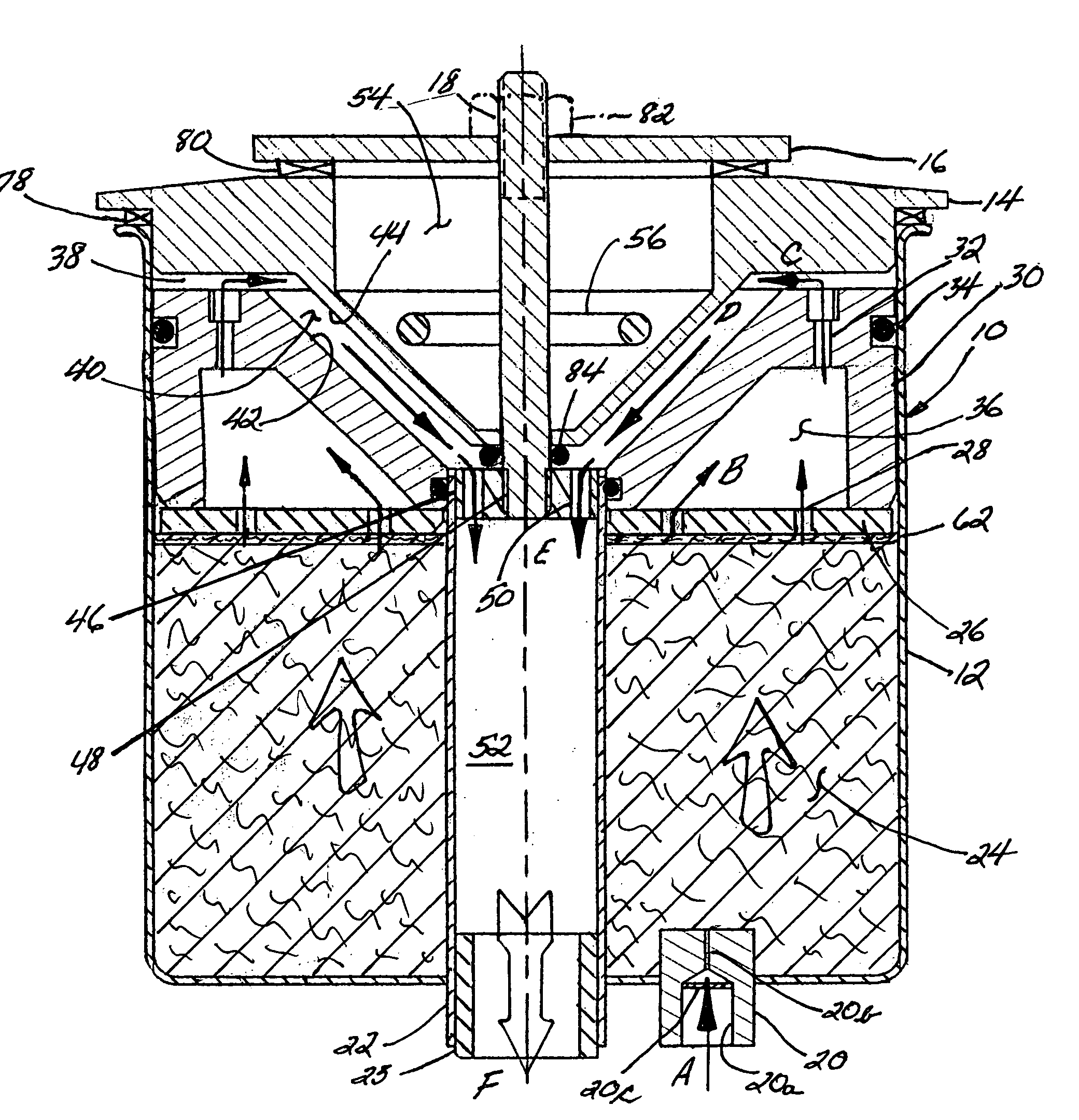
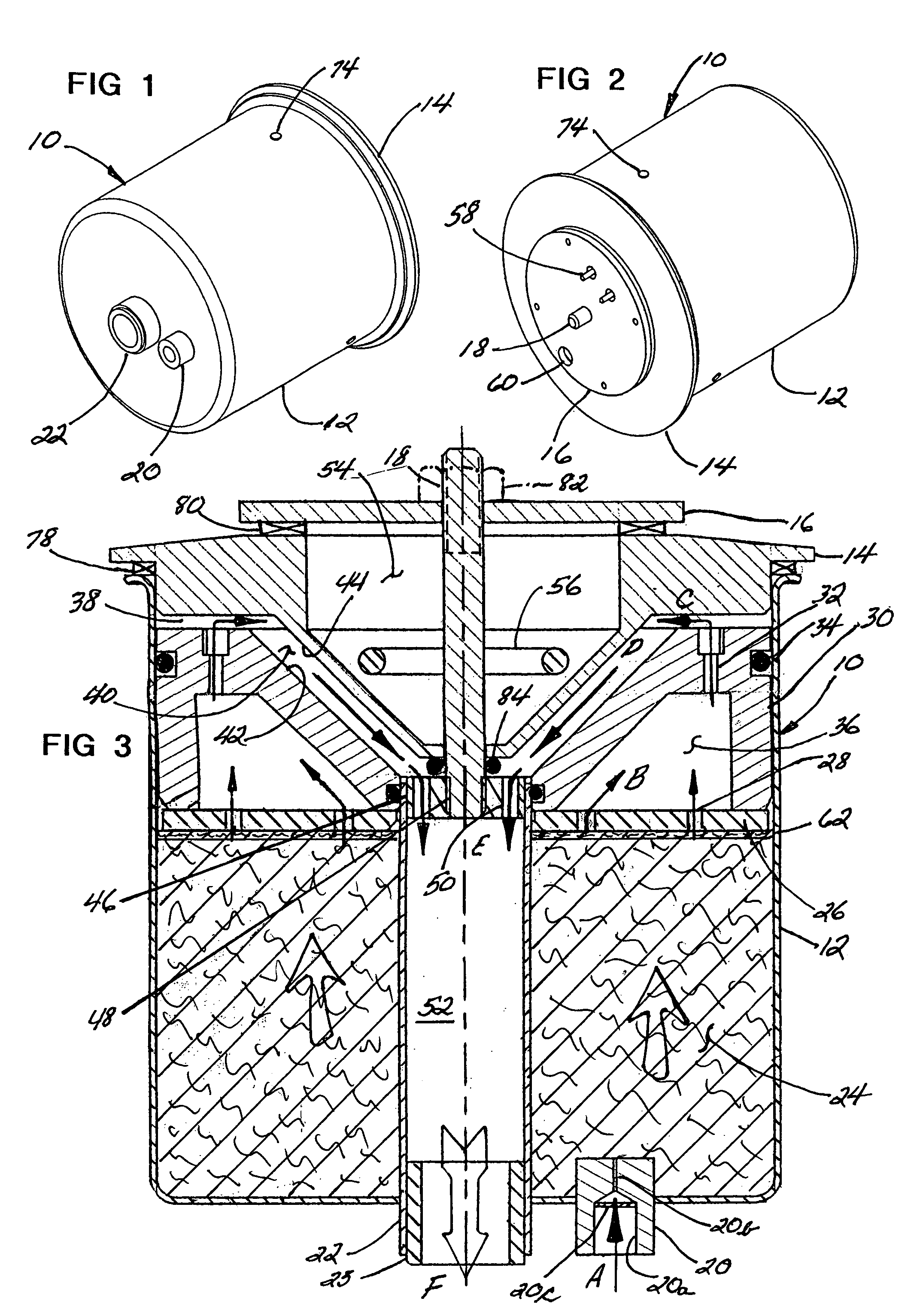
[0037]Referring now to the drawings, the preferred embodiment of the engine oil filter assembly is there shown generally at numeral 10 and includes a formed metal thin-wall canister 12 generally having a cup shape with an outwardly flanged open end thereof as shown. The typical preferred diameter is approximately 6″ and the length is also approximately 6″. Removably positioned within the lower portion of the canister 12 is a long strand of cotton fibrous filter element 24 positioned against the bottom of the canister 12 and protectively covered by a thin ⅛″ thick removable felt pad 62 positioned thereatop. The filter element 24 is designed to filter solid contaminant particulate matter from the engine oil down to approximately 0.3 microns.

[0038]Connected through the bottom of the canister 12 is an oil inlet fitting 20 having a lower central portion thereof threaded at 20a for interconnection to the oil circulating system of an internal combustion engine. A 0.020 mesh stainless steel...


PUM

PropertyMeasurementUnit
Pressureaaaaaaaaaa
Gravityaaaaaaaaaa

Abstract

An engine oil filter assembly and method for removing solid and liquid contaminants from engine oil. After solid contaminants are removed by passing the oil under engine pressure upwardly through a fibrous filter element within a lower portion of a canister, the oil is then forced through a separator after which the filtered oil under pressure decompresses. A lid having a downwardly sloping central portion is closely spaced above a similar sloping central portion of the separator to define a heating channel therebetween. A heating element in fluid isolation from the heating channel radiates heat through the central lid portion to vaporize liquid contaminants still in the oil, the vaporized contaminants discharging through a vapor vent in the lid, the decontaminated oil passing by gravity through the heating channel into a drain insert and back into the engine via an oil return port.

Description

CROSS-REFERENCE TO RELATED APPLICATIONS[0001]Not applicableSTATEMENT REGARDING FEDERALLY SPONSORED RESEARCH OR DEVELOPMENT[0002]Not applicableINCORPORATION-BY-REFERENCE OF MATERIAL SUBMITTED ON A COMPACT DISC[0003]Not applicableBACKGROUND OF THE INVENTION[0004]1. Field of the Invention[0005]This invention relates generally to bypass filtration units for internal combustion engines and more particularly to an engine oil filter which is preferably reusable and provides both solid and liquid contaminant removal from engine oil.[0006]2. Description of Related Art[0007]Filtration or the removal of solid contaminants from engine oil via a canister bypass or flow-through filter is well known. As engine oil is circulated throughout an operating engine, solid contaminants are picked up and carried within the engine oil and, if not properly removed, can result in excessive or premature wear of the closely fitting internal engine components. The engine oil, typically operating at a pressure of...

Claims


Application Information

Patent Timeline
IPC IPC(8): B01D37/00
CPCB01D29/055B01D35/185B01D2201/4015Y10S210/17
Inventor GUYNN, STACY D.
Owner GUYNN STACY D
Why Eureka
Try Eureka