Sliding member

Inactive Publication Date: 2008-07-15
DAIDO METAL CO LTD
View PDF4 Cites 30 Cited by
  • Summary
  • Abstract
  • Description
  • Claims
  • Application Information

AI Technical Summary

Benefits of technology

[0007]The present invention has been made in view of the above-described circumstances, and an object thereof is to provide a sliding member capable of reducing the oil film pressure at both ends in the axial direction in the initial sliding state, and preventing occurrence of the oil film destruction and accordingly the seizure or the like due to the partial metallic contact as much as possible.
[0009]According to the first aspect, the recesses are formed on the sliding surface so that the total area of openings of the recesses per unit area becomes gradually larger as it gets closer to the end side. For this reason, the lubrication oil is stored in the recesses in the initial sliding state, the pressurized area decreases in the end portion of the sliding surface due to the recesses, and the strength of the sliding member is adequately reduced, whereby the sliding surface wears in conformity with the deflection of the mating member. At this time, in the case where the lubrication oil is not sufficiently supplied from a lubricant pump on startup of an engine or the like, the lubrication oil in the recesses on the sliding surface is supplied between the sliding surfaces to prevent the seizure as much as possible. Accordingly, the sliding surface is worn at an early stage, while the lubrication oil prevents the seizure, so as to form a conformed surface in the initial sliding state.
[0011]According to the second aspect, the opening area decreases as wear of the sliding surface progresses, and the pressurized area increases in reverse proportion thereto so that the bearing surface pressure acceptable by the sliding surface is increased. For this reason, fast progress of the wear at the early stage is stopped by the formation of the conformed surface while the holes remain without being entirely whittled or ceasing to exist, so that the lubrication oil can be stored in the remaining holes in the initial sliding state, the seizure can be prevented.
[0019]According to the sixth aspect, the depth of the hole or the groove formed on the sliding surface is not too shallow, and so all the holes and grooves will not cease to exist even if the sliding surface wears by a certain amount in the initial sliding state. Therefore, the oil retaining property of the holes or the grooves will be kept without being extremely reduced. Furthermore, the hole and groove are not too deep to reduce the strength of the sliding member more than necessary.

Problems solved by technology

Therefore, the bearing surface load sometimes rises extremely in the portions to cause breakage of an oil film and accordingly, the sliding operation in a partial metallic contact state has caused seizure or the like.

Method used


Image

  • Sliding member
  • Sliding member
  • Sliding member

Examples


Embodiment Construction

[0034]Hereafter, a description will be given by using FIGS. 1 to 6 with respect to a first embodiment in which a sliding member of the present invention is applied to a main bearing supporting a crankshaft of an engine.

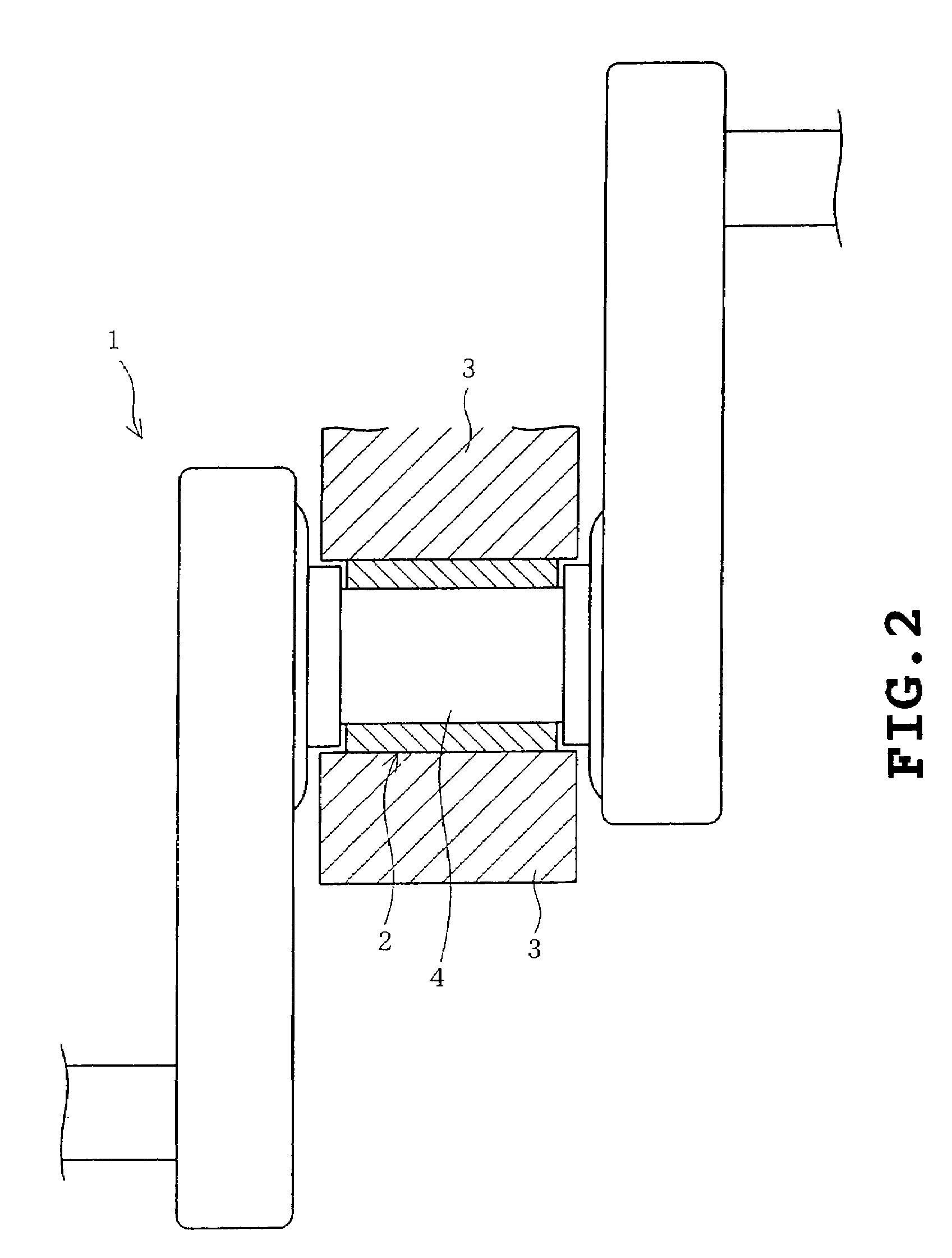
[0035]As shown in FIG. 2, a main bearing 2 which is a sliding member for supporting a crankshaft 1 has its outer circumferential surface fitted with a housing 3, and rotatably supports a main shaft 4 (a mating member) of the crankshaft 1 on its inner circumferential surface. As shown in FIGS. 6A and 6B, the main bearing 2 is cylindrically formed by putting two bearing halves 2a of a semi-cylinder shape together. The bearing halves 2a are constituted by placing a copper bearing alloy layer 6 on a steel back metal 5 as shown in FIG. 3 showing its cross section. Also, the bearing alloy layer 6 may be made of aluminum, and may be covered with an overlay layer.

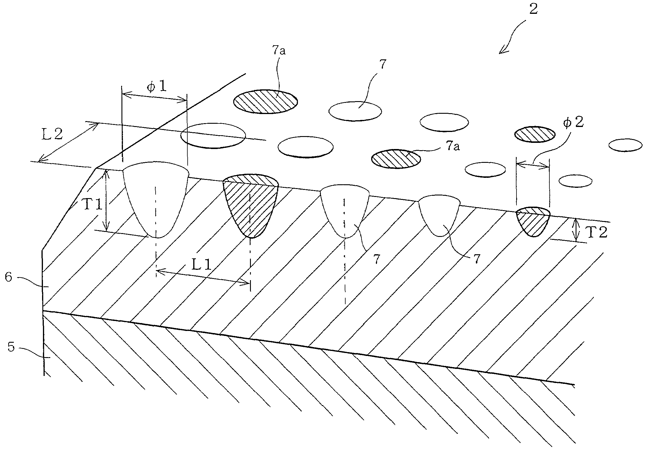
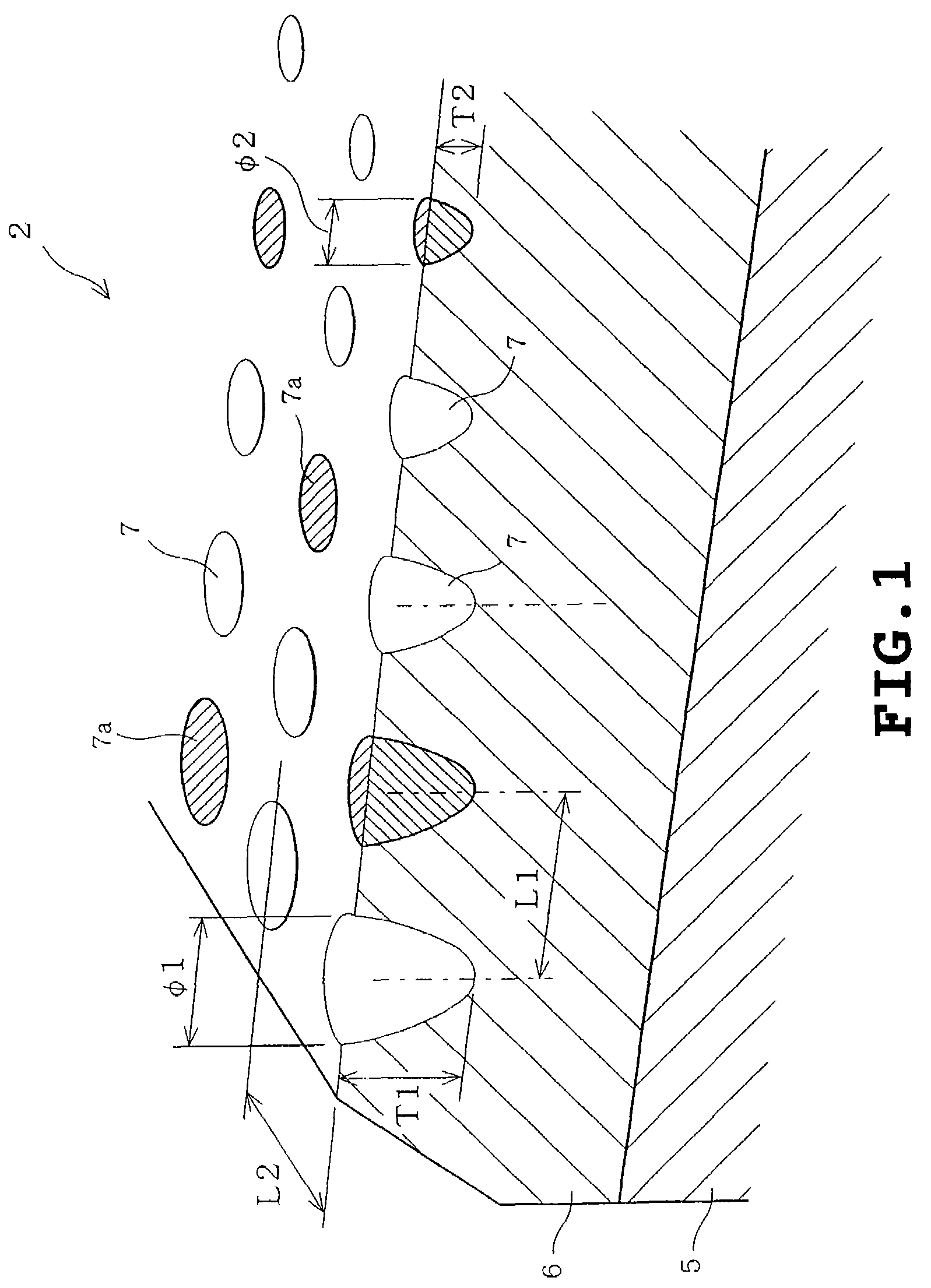
[0036]As shown in FIG. 1, there are provided holes 7 as recesses in both end portions in an axial direction of a s...


PUM

PropertyMeasurementUnit
depthaaaaaaaaaa
mean diameteraaaaaaaaaa

Abstract

In order to improve conformability of a sliding surface of a sliding member in an early state of sliding, there is provided a sliding member in which a plurality of holes are formed on a sliding surface, and the diameters (or the opening area) of the holes on the sliding surface are arranged so as to become gradually large as it gets closer to both ends in an axial direction from the center side in the axial direction. This feature decreases the pressurized area as it gets closer to the ends of the sliding surface so that it wears at an early stage, whereby a conformed surface following the deflection of a mating member is provided.

Description

BACKGROUND OF THE INVENTION[0001]The present invention relates to a sliding member in which a high load acts on an end side of a sliding surface thereof, and particularly to a sliding member for a main bearing for supporting a crankshaft of an engine, for example.[0002]In general, an engine used for an automobile or the like is constructed so that a crankshaft and a piston are mutually coupled via a connecting rod. This engine generates driving force by using the connecting rod to convert up-and-down movement (vertical movement) of the piston into rotational movement and to transmit it to the crankshaft. Because the crankshaft obtains the rotational movement by converting the up-and-down movement as described above, a main shaft thereof is rotated in a so-called elliptical orbit, that is, in a deflected state in an radial direction if using a grandiloquent phrase.[0003]However, if the crankshaft is deflected during sliding operation before the main bearing supporting it conforms to ...

Claims


Application Information

Patent Timeline
Patent Type & Authority Patents(United States)
IPC IPC(8): F16C17/00F16C33/00F16C3/14F16C9/02F16C33/10F16C33/14F16C33/24
CPCB23K26/383B23K26/385F16C9/02F16C17/02F16C33/1065F16C33/24F16C33/103F16C33/1095F16C33/14F16C2240/42F16C2240/44B23K26/384B23K26/389F16C2220/62F16C2223/08F16C2240/40
Inventor FUJITA, MASAHITOTSUJI, HIDEOSHIBAYAMA, TAKAYUKI
Owner DAIDO METAL CO LTD
Why Eureka
Try Eureka