

End mill bit with notched teeth
- Summary
- Abstract
- Description
- Claims
- Application Information
AI Technical Summary
Benefits of technology
Problems solved by technology
Method used
Image

Examples
Embodiment Construction
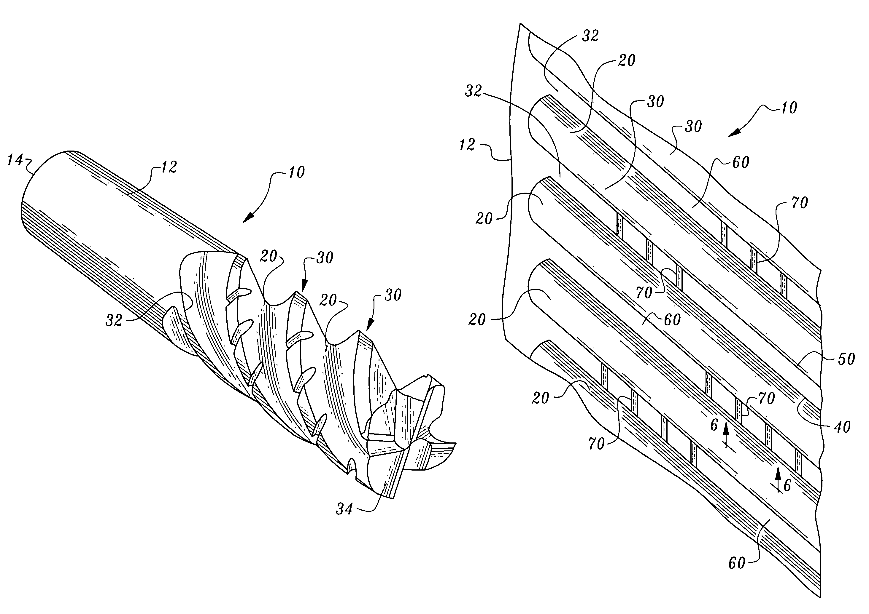
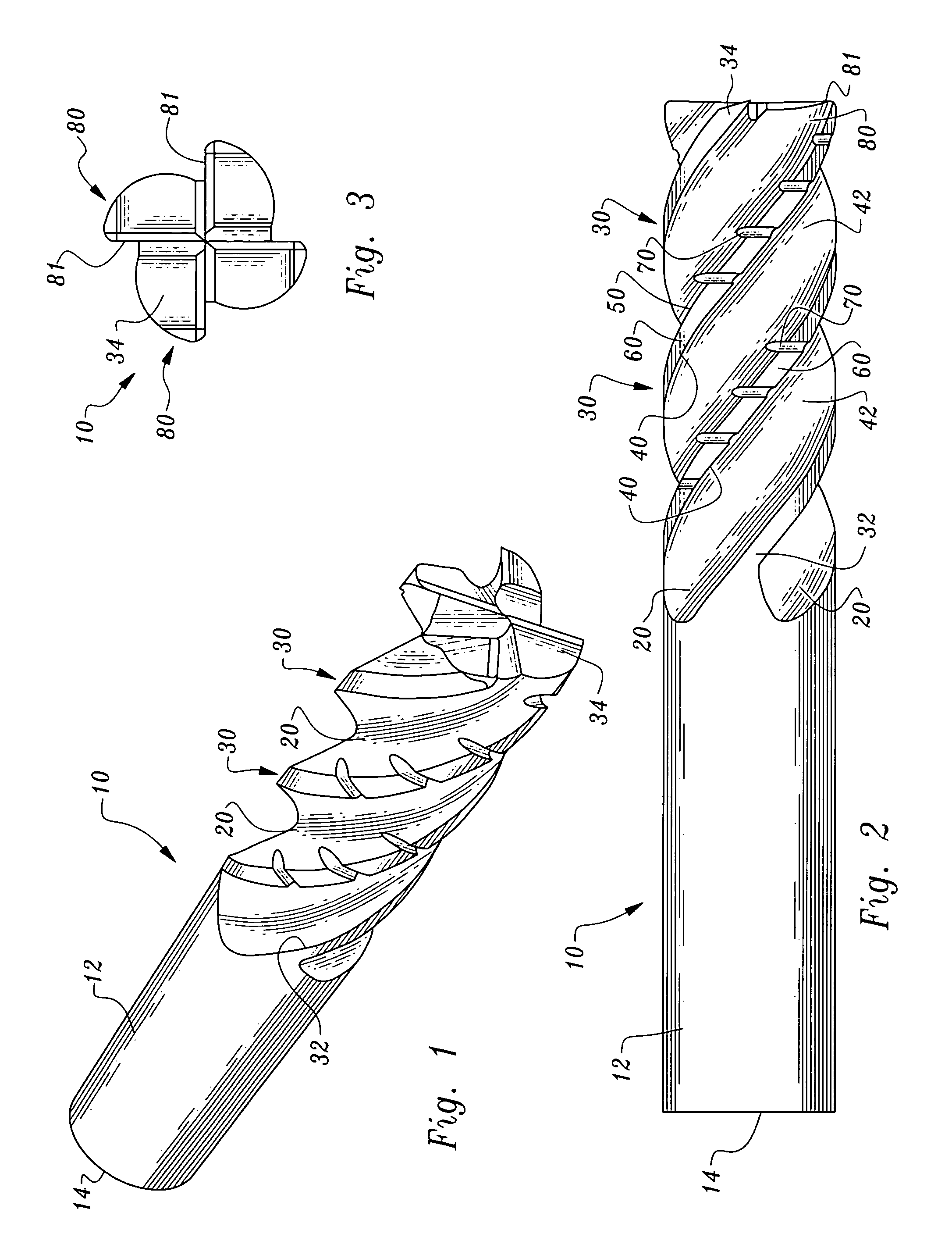
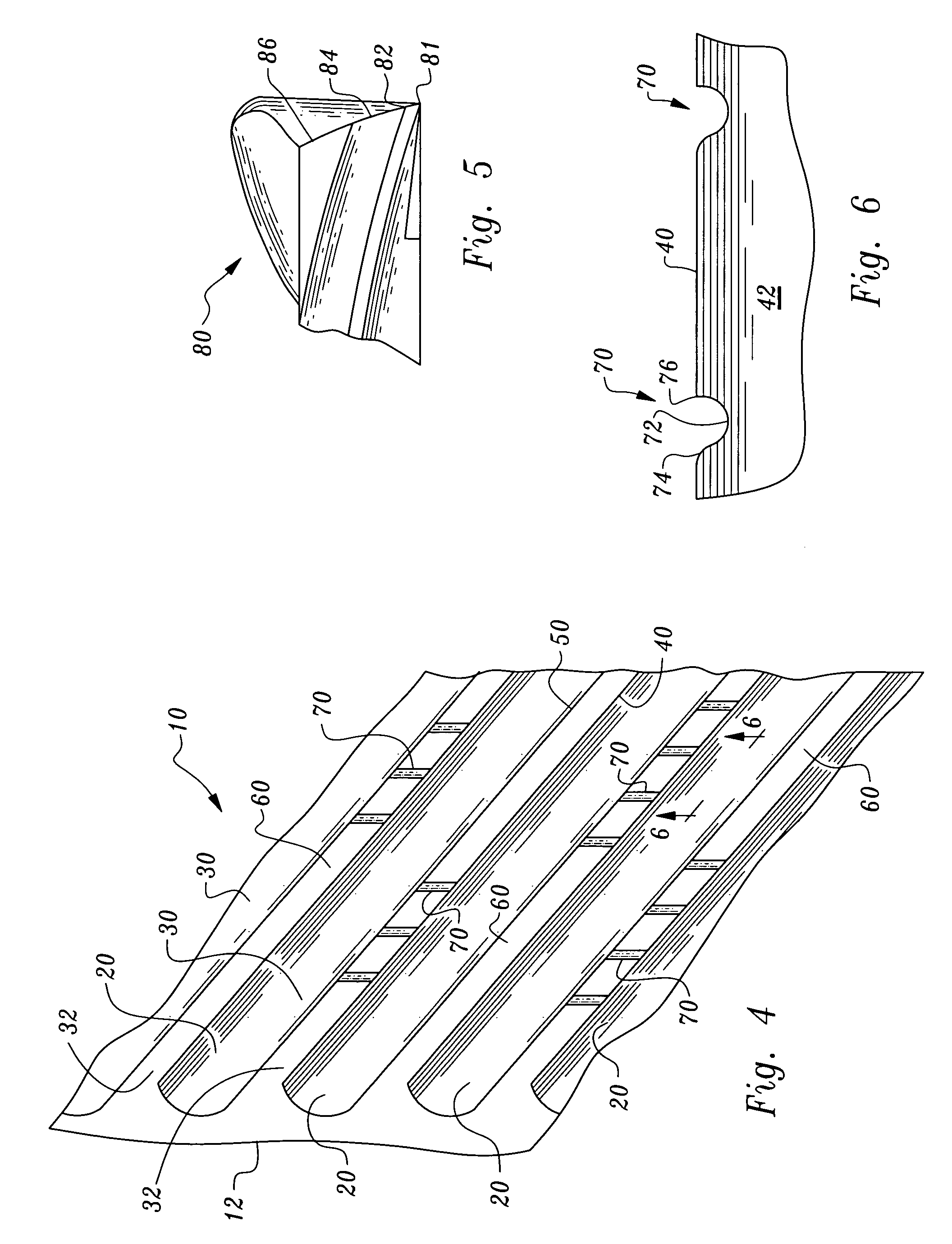
[0025]Referring to the drawings, wherein like reference numerals represent like parts throughout the various drawing figures, reference numeral 10 (FIGS. 1-3) is directed to an end mill illustrating this invention according to a preferred embodiment. This end mill 10 is particularly configured to cut a work piece with a minimum of vibration, by including notches, referred to as knuckles 70, in the cutting edge 40 of portions of a majority, and preferably all, of the teeth 30 of the end mill 10. The end mill 10 can thus travel quickly and precisely through a work piece with a minimum of vibration and producing a smooth and precise cut.
[0026]In essence, and with particular reference to FIGS. 1-3, basic details of the end mill 10, according to this preferred embodiment, are described. The end mill 10 is formed with a plurality of flutes 20 extending helically along a long axis of the end mill 10 so that the flutes 20 separate adjacent teeth 30 of the end mill 10. Each tooth 30 includes...
PUM
 Abstract
Description
Claims
Application Information