Gas and oil sealing in a rotary valve

a technology of gas and oil sealing and rotary valves, which is applied in the direction of valve arrangements, oscillatory slide valves, machines/engines, etc., can solve the problems of inability to design a satisfactory gas and oil sealing arrangement, large total leakage gap, and no commercial success

Active Publication Date: 2008-07-22
BISHOP INNOVATION PTY LTD
View PDF13 Cites 4 Cited by
  • Summary
  • Abstract
  • Description
  • Claims
  • Application Information

AI Technical Summary

Benefits of technology

[0016]A successful gas sealing system should preferably satisfy six criteria. Firstly, it should seal high pressure combustion gas with a minimum of leakage. This leakage is referred to as “blow-by”. Blow-by contains unburned hydrocarbons that are tightly regulated by emissions legislation around the world. Secondly, a successful gas sealing system should have minimal crevice volume. Thirdly, the arrangement must be capable of preventing the blow-by gases being discharged into the exhaust port where they appear as HC (hydro carbon) exhaust emissions. Fourthly, the gas sealing elements should produce minimal drag on the rotary valve in order to minimise frictional losses of the engine. Fifthly, the assembly should be capable of easy assembly in a mass production environment. Finally, the assembly should be capable of economic manufacture in a mass production environment. None of the prior arrangements provide solutions to all these criteria.

Problems solved by technology

Large numbers of rotary valve arrangements have been proposed but none have achieved commercial success.
One of the major contributing factors to this lack of success is the failure to design a satisfactory gas and oil sealing arrangement.
As there are at least four such intersection points per assembly, the total leakage gap has the potential to be large.
Both the sealing systems disclosed in U.S. Pat. No. 4,036,184 (Guenther) and U.S. Pat. No. 4,852,532 (Bishop) do not work satisfactorily due to excessive leakage from the seal pack.
So great is this leakage that it is unlikely that the engines using these arrangements will be able to be started using conventional starter motors.
Leakage from the operating engine will be so great that the efficiency will be unacceptably low and the exhaust emissions unacceptably high.
As there are four corners from which this discharge can take place, the total leakage area is very large.
In the absence of specific measures, of which none are disclosed, to control the discharge from the portion of the circumferential seals located outside the axial seals, leakage will be unacceptably high for any modern engine.
Although the arrangement disclosed in U.S. Pat. No. 5,526,780 (Wallis) satisfactorily addressed the gas leakage issues it required two additional sealing elements and was found to have other problems.
In particular this arrangement is particularly difficult to assemble and has excessive crevice volume, particularly when measured relative to the combustion chamber volume on engines with small cylinder capacity.
Consequently friction drive losses are high.
Finally, the seal arrangement is very difficult to assemble as the inner partial ring seals have to be aligned during assembly such that the inner ends of these inner partial ring seals sit outside the small lugs at either end of the axial seals.
As the required clearance between the lugs and the inner end of these inner partial ring seals is small, correct alignment during assembly is very difficult and not conducive to high volume production.
Although the crevice volume issues relating to the arrangement disclosed in U.S. Pat. No. 5,526,780 (Wallis) were extensively considered, it was subsequently found that in engines with small cylinder capacity the crevice volume was still sufficiently large to adversely affect the engines performance.
The fuel / air mixture in these crevice volumes cannot be burned during the normal combustion process and this consequently results in poor engine fuel economy and performance, and high exhaust emissions.
Crevice volumes remote from the spark plug are particularly detrimental, as the expanding flame front pushes unburnt gases into these crevice volumes and the rapidly increasing cylinder pressure means the density of the unburnt gases in the crevice volume rises rapidly.
This can only be achieved by allowing the high pressure gas to migrate into those areas surrounding the sealing elements in their slots.
As a result, there is a large crevice volume formed between these seals and the mating groove in the valve and between the ring seals themselves.
This problem was exacerbated by the fact that this crevice volume was located a large distance from the spark plug, and consequently the density of the mixture filling this area was high and consisted mainly of unburnt gases.
Secondly, the ring seals were located at the end of the axial seals leaving a long cavity between the axial extremity of the window and the ring seals.
These two issues resulted in unacceptably large crevice volumes with resulting poor performance and high emissions.
Two of these solutions U.S. Pat. No. 4,036,184 (Guenther) and U.S. Pat. No. 4,852,532 (Bishop) do not seal adequately.
None of the prior arrangements provide solutions to all these criteria.
Both suffer from excessive leakage from the seal pack as previously described.
This, combined with the fact that the valve rotates at one quarter (¼) of the engine speed, means the arrangement will necessarily have very limited breathing capacity.
The ability to form long openings in the valve periphery introduces design constraints on axial flow rotary valves that are not present on arrangements employing a single radial flow rotary valve per cylinder.
Placing the circumferential seal axially outboard of the axial seal results in a large crevice volume between the axial extremities of the window and the circumferential seal.
As this crevice volume is remote from the spark plugs, it will be filled predominately with unburned gases further exacerbating the problem caused by this crevice volume.
This is, however, an arrangement that cannot work.
The circumferential seal of the type depicted in U.S. Pat. No. 4,036,184 (Guenther) is unsatisfactory as it is too stiff to conform to the surface of the rotary valve.
This will inevitably result in leakage across the top of the seal and destabilisation of the sealing mechanism.
The result will be massive leakage across the sealing surface of the circumferential seal.
This spring arrangement would act to deflect the axial seals into the opening in the valve's periphery, hence potentially causing them to have a collision with the closing edge of the opening and destroying the seals.
In this prior art arrangement it is paradoxical that the circumferential seals (that must conform to the peripheral surface of the valve in order to seal) are radially deeper in section compared to the axial seals, which are required to be stiff.
However this arrangement would have very little breathing capability.
A radial flow arrangement with two rotary valves per cylinder (ie. separate valves for inlet and exhaust) would in part address this breathing issue by allowing the use of long openings in the valve but would not work with the axial seal arrangement as depicted in U.S. Pat. No. 4,036,184 (Guenther).
This arrangement could only be made to work by substantially increasing the stiffness of the axial seals by increasing their depth.
A twin valve arrangement would create additional crevice volume and leakage problems as there are now two seal arrays, which doubles both the TELA and crevice volume.
In addition to excessive stiffness problems the circumferential seals depicted in U.S. Pat. No. 4,036,184 (Guenther) have an additional problem.
The large size of the seal means there will be an excessive crevice volume around the circumferential seal.
In the case of U.S. Pat. No. 4,852,532 (Bishop), the long length of the circumferential seal results in excessive crevice volume around the seal despite the fact it is radially small.
Such an engine will be unacceptable from an emissions perspective.
There is no known mass production method of forming these blind ended slots.
They could be manufactured by electro discharge machining but this is a slow process and the high depth of these slots would make the process even slower.
However, this feature is the cause of the crevice volume problems.
Finally these prior art arrangements are difficult to assemble in a mass production situation.
Secondly, it must act in combination with the gas sealing elements to manage the passage of blow-by gases into an area where it can be disposed of without creating emissions.
Such an arrangement has been demonstrated to not work as a satisfactory oil seal.
In practice, these blow-by gases contain unburnt fuel which when discharged into the oil system over time, heavily contaminates the oil degrading its lubricating properties.
The continuous discharge of unburnt fuel into the lubricating oil system causes the volume of oil in the system to increase over time.
Although methods of ameliorating this problem are disclosed in U.S. Pat. No. 5,509,386 (Wallis), none are totally effective as they merely reduce the frequency that the non-rotating annular member is blown off the radially disposed face.

Method used


Image

  • Gas and oil sealing in a rotary valve
  • Gas and oil sealing in a rotary valve
  • Gas and oil sealing in a rotary valve

Examples


second embodiment

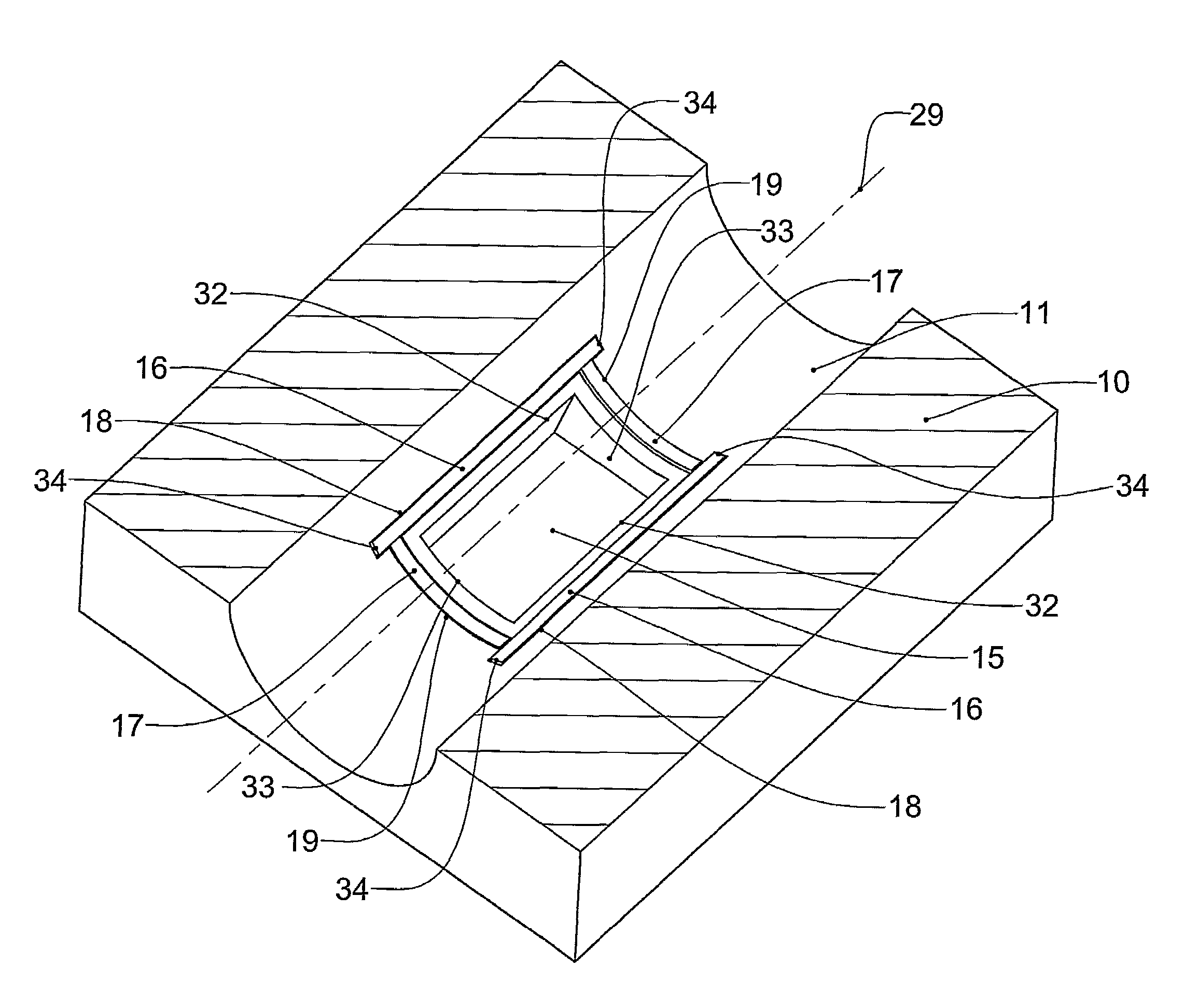
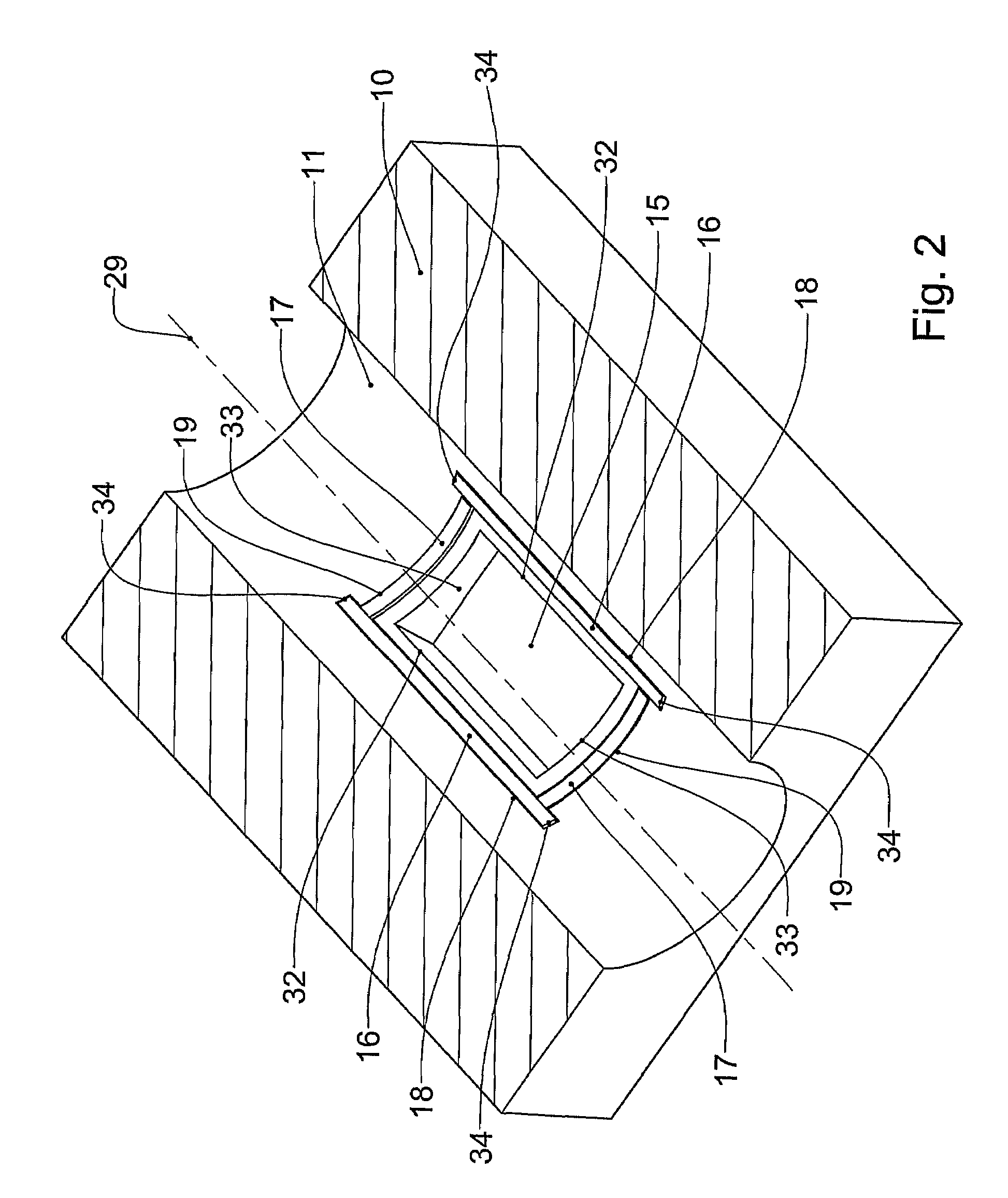
[0100]FIG. 7 is a part section through the centre of one end of an axial slot 18 of a rotary valve assembly in accordance with the present invention, showing details of an alternative spring design. Spring 21c is different to that previously shown in that the upper leg 41c is shorter than the lower leg 42c. Spring 21c has the advantage that it maximises the allowable spring movement whilst maintaining the line of action of the spring on axial seal 16 close to or outside openings 7, 8 and maintaining an acceptable stress level within the spring. The short upper leg 41 applies the radial load to axial seal 16 outside openings 7, 8. The longer lower leg 42 provides the necessary radial movement required to ensure an adequate spring force is applied to axial seal 16 in all operating conditions.

[0101]A function of the springs 21 as described above is to block the flow of combustion gases between the undersides 5 of the axial seals 16 and the roots 6 of the axial slots 18 to the area betw...

third embodiment

[0102]In the event that further reduction in the TELA is required, additional flexible elements may be introduced above springs 21. the present invention shown in FIG. 9 has flexible elements in the form of cylindrical seals 28 which are located above and in contact with springs 21. Cylindrical seals 28 are disposed in recesses formed in the underside of the ends of axial seals 16c. Cylindrical seals 28 have a width close to that of axial slots 18 and are made from an elastomeric material such as rubber. When assembled, seals 28 span between the circumferentially innermost sides 24 and circumferentially outermost sides 20 of axial slots 18. Cylindrical seals 28 block the type F leakage area that feeds the type A & B leakage area. In the event there is 1 mm between the top of cylindrical seals 28 and the top of axial seals 16c, the feed area is approximately reduced to 4×(1×0.01)=0.04 mm2. The TELA of this arrangement is now 0.04 mm2 or less than that of a conventional piston ring. A...

fourth embodiment

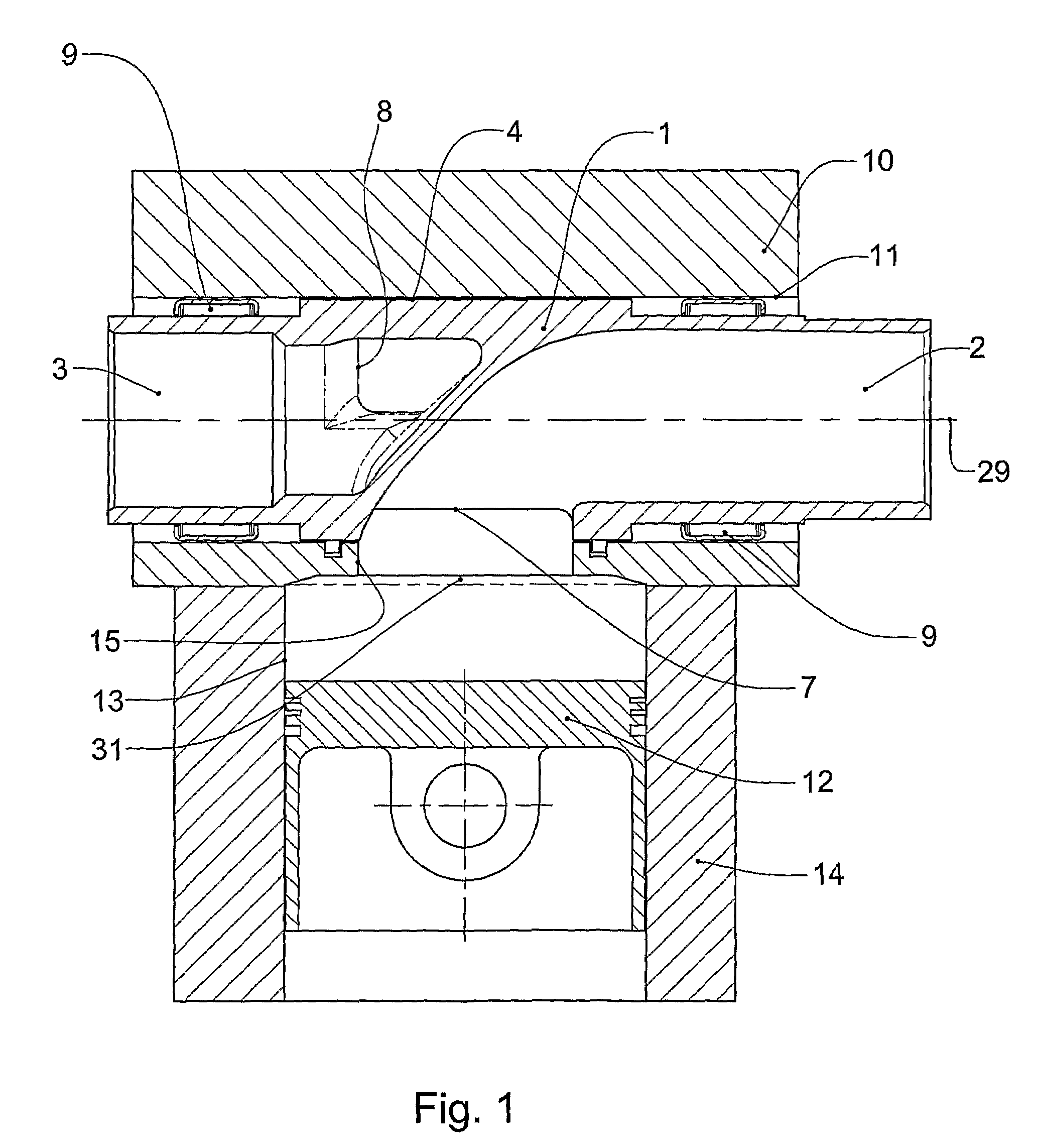
[0104]FIGS. 10 and 11 show sections of a rotary valve assembly in accordance with the present invention. FIGS. 10 and 11 are the same views as FIGS. 2 and 3 respectively, but with modifications added to enable mass production machining techniques to be utilised in the manufacture of the axial slots and circumferential seal slots. The seal slots previously discussed in reference to FIGS. 2 and 3 are square ended slots that require the use of techniques not generally associated with mass production to manufacture. Typically these square ended slots are manufactured using an EDM (electro discharge machining) process which is time consuming and expensive.

[0105]Bore 11a has been stepped at both ends of cylinder head 10. This radial step is deeper than the depth of axial slots 18a. Consequently axial slots 18a can be manufactured rapidly and economically by through-broaching the minimum diameter portion (i.e. the non-stepped portion) of bore 11a in the axial direction. After axial slots 1...


PUM


Abstract

A sealing system for an axial flow rotary valve internal combustion engine comprising an array of floating gas seals and an optional oil sealing system. The array of floating seals surrounding a window (15) in the bore (11) of the cylinder head (10) through which the ports (2, 3) of the valve (1) communicate with a combustion chamber (31). The array of floating seals comprising axial seals (16) and circumferential seals (17) housed in slots (18, 19) in the bore of the cylinder head wherein the circumferential seals are disposed axially between the ends of the axial seals.

Description

TECHNICAL FIELD[0001]The present invention relates to gas and oil sealing arrangements for rotary valve internal combustion engines, and in particular to axial flow rotary valves that accommodate one or more ports in the valve terminating as openings in the valve's periphery.BACKGROUND[0002]The present invention is particularly concerned with axial flow rotary valve arrangements that have long windows (i.e. window lengths, as measured in the axial direction, greater than 50% of the cylinder bore diameter), in order to maximise the breathing capacity of the internal combustion engine to which the rotary valve assembly is fitted. Maximum breathing capacity is a dominant consideration in modern engines, where manufacturers seek to gain the greatest power output from the smallest engine size for fuel consumption and emissions reasons.[0003]During rotation of an axial flow rotary valve, openings in the periphery of the valve are arranged to periodically communicate with a similar window ...

Claims


Application Information

Patent Timeline
Patent Type & Authority Patents(United States)
IPC IPC(8): F01L7/16
CPCF01L7/02F01L7/023F01L7/16F01L7/024F01L2820/01
Inventor THOMAS, ANDREW DONALDWALLIS, ANTHONY BRUCE
Owner BISHOP INNOVATION PTY LTD
Why Eureka
Try Eureka