Axial bearing

a technology of thrust bearings and axial bearings, which is applied in the direction of sliding contact bearings, crankshafts, machines/engines, etc., can solve the problems of not being able to drill directly from the recess to the through opening, contributing heavily to the total cost of thrust bearings, and collapse of lubricating oil pressure, etc., to achieve cost-effective and safe effects

Active Publication Date: 2008-07-22
BORGWARNER INC
View PDF10 Cites 36 Cited by
  • Summary
  • Abstract
  • Description
  • Claims
  • Application Information

AI Technical Summary

Benefits of technology

[0005]Based on this, it is the object of the present invention to provide a thrust bearing of the type described above, in which the bearing surfaces can be supplied with lubricating oil in a cost effective and safe manner.
[0006]The invention is based on the concept that a radial drilling of the bearing body can be avoided when the oil supply channel can be brought into the bearing body from the surface side. According to the invention the at least one oil supply channel is therefore made to be a groove. Thereby, it is possible to manufacture the bearing body, together with the grooves, by means of a drop forging, milling or stamping process. Drilling and closing of additional channels is no longer required, whereby the manufacturing cost of the thrust bearing is considerably reduced.
[0007]In a preferred embodiment of the invention, the bearing has an oil pocket, which is subjected to lubricating oil and which extends over a part of the periphery of the bearing body, concentrically to the through opening for the shaft, and starting from which the oil supply channel extends up to the through opening. The oil pocket acts as a reservoir for the lubricating oil and thus supports a steady oil supply for the bearing.
[0011]In order to be able to drain the oil after it has flowed through the bearing, the bearing surface is encircled by an oil drain groove, by way of which the lubricating oil can flow downward into the bearing housing of the turbo charger. Since this oil drain groove is created radially between the bearing surface and the oil pocket, it is crossed by at least one oil supply channel. To avoid an excessive pressure loss over the oil drain groove, the area of cross section of the oil supply channel is appropriately considerably larger than the area of cross section of the oil drain groove.
[0012]The shape of the oil supply channels can be altered and can be made to suit the desired application. It is necessary on the one hand to determine the load bearing capacity of the bearing and, on the other, to minimize the frictional loss in the lubricating film. These two effects run counter to each other, which means that the more oil is delivered to the bearing area and the larger the cross section of the grooves is, the higher is the load bearing capacity of the bearing. On the other hand, if the rpm of the shaft is very high, a large amount of frictional force comes into play, which in turn leads to corresponding mechanical losses, with the result that the efficiency of the bearing is impaired when a large amount of oil is supplied. In a preferred embodiment of the invention, the oil supply channel has essentially a rectangular, V-shaped, semi-circular or semi-elliptical cross section. These shapes can be easily produced by a drop forging or a milling or stamping process.

Problems solved by technology

The disadvantage of this construction form is that, because of the flat design of the bearing body, it is not possible to drill directly from the recess to the through opening.
Drilling these additional channels and again closing them is a very elaborate process, contributing heavily towards the total cost of the thrust bearing.
Additionally, the is a risk that, in case of any deficiency in closing a channel, it could become free later, which would cause a collapse of the lubricating oil pressure and consequently damage to the bearing.

Method used


Image

  • Axial bearing
  • Axial bearing

Examples


Embodiment Construction

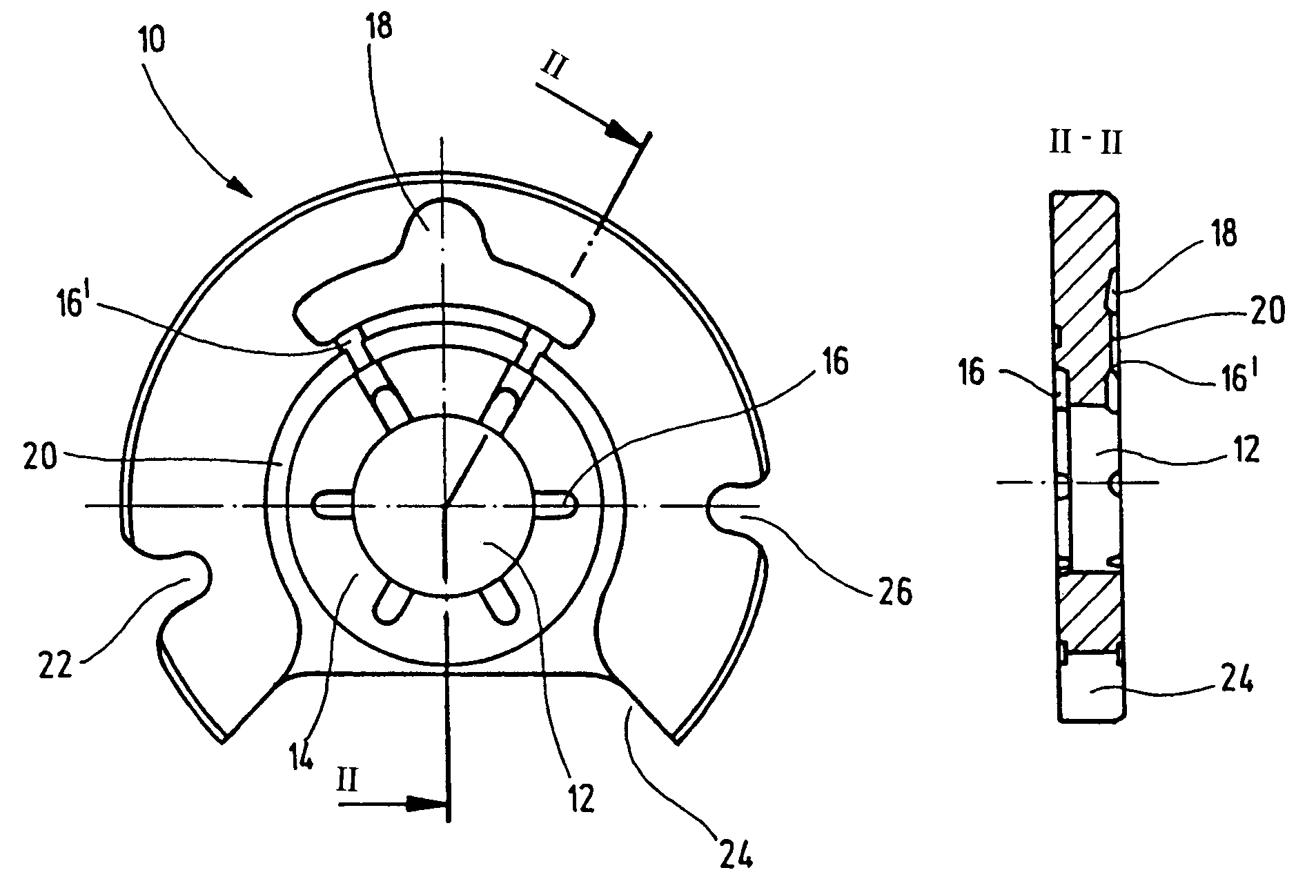
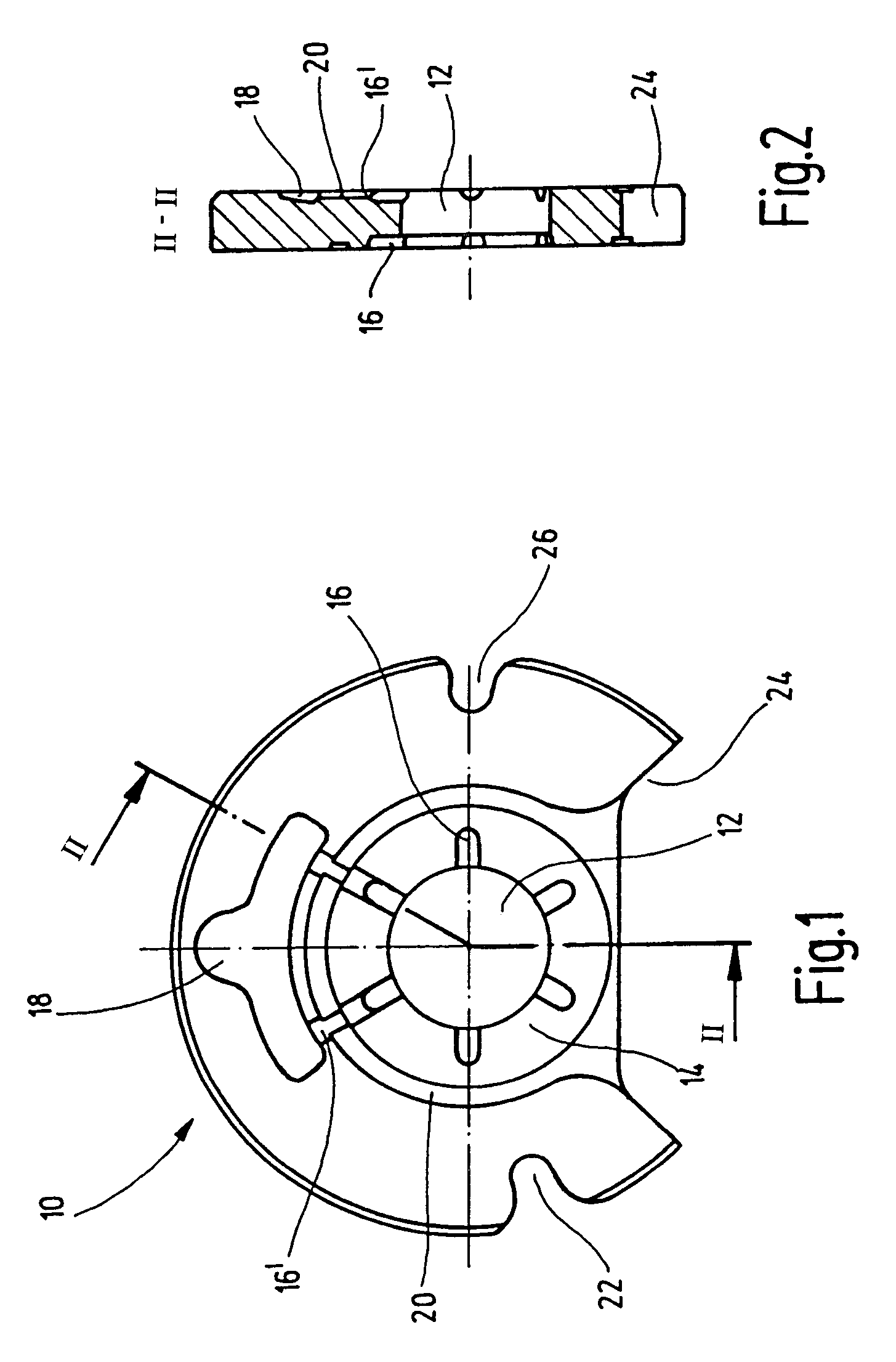
[0017]The thrust bearing 10 shown in the drawing has a central through opening 12 for a shaft, for example, the shaft of a turbo charger. The through opening 12 is surrounded by six wedge surfaces 14 (not shown in detail), which together constitute the bearing surface of the bearing. The wedge surfaces 14 are separated from each other in the peripheral direction by six grooves 16, 16′, which are arranged in a star-like formation and over which the wedge surfaces are supplied with lubricating oil. While the grooves 16 penetrate part of the bearing surface radially, the grooves 16′ extend radially outwards and open into the oil pocket 18. The bearing surface is further surrounded by a peripheral groove 20, through which the lubricating oil can flow out after flowing through the bearing, wherein the area of cross section of this groove is smaller than the area of cross section of the grooves 16′. This is done to ensure adequate oil flow to the shaft. The edge slots 22, 24, 26 help in t...


PUM


Abstract

A thrust bearing, in particular for a turbo charger, has an essentially disc shaped bearing body (10) with a central through opening (12) for a shaft, at least one bearing surface (14) surrounding the through opening (12) for a collar which is placed on the shaft, and at least one oil supply channel which leads from a radially outer region of the bearing body to the through opening (12). In order to realize a cost effective manufacture of the thrust bearing it is proposed according to the invention that the at least one oil supply channel is designed to be a groove (16′).

Description

BACKGROUND OF THE INVENTION[0001]1. Field of the Invention[0002]The invention relates to a thrust bearing (axial bearing), in particular to a turbo charger, having an essentially disc shaped bearing body with a central through opening for a shaft, having at least one bearing surface surrounding the through opening for a collar which is placed on the shaft and also having at least one oil supply channel, which leads from a radially outer region of the bearing body to the through opening. The invention further relates to a turbo charger with a thrust bearing of such type.[0003]2. Related Art of the Invention[0004]The shaft of a turbo charger, for example, rotates with a high speed and therefore must be supported both axially as well as radially, since, depending on the load condition, axial forces are generated either through the compressor wheel or the turbine wheel. A thrust bearing of the type mentioned at the outset and which is fixed firmly in the shaft housing is used for absorb...

Claims


Application Information

Patent Timeline
Patent Type & Authority Patents(United States)
IPC IPC(8): F16C17/04F16C33/10
CPCF01D25/168F01D25/18F16C33/1065F16C33/1075F16C17/047F05D2240/52F05D2240/53F16C2360/24F05D2220/40
Inventor KRAUSS, PAULWEINITSCHKE, THOMASEGGERT, HELMUTSCHAPPERT, KLAUSSTOLL, NORBERT
Owner BORGWARNER INC
Why Eureka
Try Eureka