Super plastic design for CHF pacemaker lead

a technology of lead and super plastics, applied in the direction of internal electrodes, transvascular endocardial electrodes, therapy, etc., can solve the problems of paralysis or fatal stroke, damage to insulation, blood clot formation in some patients, etc., to prevent the retraction of the lead, the effect of better trade-off of insertability and stability

Inactive Publication Date: 2008-07-22
PACESETTER INC
View PDF21 Cites 13 Cited by
  • Summary
  • Abstract
  • Description
  • Claims
  • Application Information

AI Technical Summary

Benefits of technology

[0011]In operation, the lead would be inserted in an appropriate location and then a deflecting guide wire or introducer would be used to bend the lead to form it into a shape around corners and wedge against the walls of a vein, preventing its retraction. As another subtlety to this method, the super plastic titanium becomes more plastic with cold working. In other words, a physician could bend the lead back and forth until it became ductile to satisfy the physician's preferences. In this manner, the physician is able to “tune” the ductility of the lead to a better trade off of insertability and stability.

Problems solved by technology

The reason for this is that implanted electrodes can cause blood clot formation in some patients.
If a blood clot were released arterially from the heart left side, as for example the left ventricle, it could pass directly to the brain potentially resulting in a paralyzing or fatal stroke.
The significance of a single lead for positioning only in the left ventricle is that it is easier and less time consuming to install only one lead rather than two and, additionally two leads can “saw” against each other where they cross in the RA (right atrium), potentially resulting in damage to their insulation.
Cardiac leads intended for use in providing both cardiac pacing and defibrillation in the left heart via the coronary sinus region have previously been difficult to position due to the tortuous venous routes of the human anatomy.
Moreover, to provide both pacing and defibrillation of both the left atrium and the left ventricle from the coronary sinus region with multiple leads employing the appropriate types of electrodes is extremely difficult given the space constraints to accommodate multiple leads in the coronary sinus region.
Hence, such known implants have been too cumbersome, difficult, and time consuming to perform and likely resulted in compromised performance or system malfunction.

Method used


Image

  • Super plastic design for CHF pacemaker lead
  • Super plastic design for CHF pacemaker lead
  • Super plastic design for CHF pacemaker lead

Examples


Embodiment Construction

[0020]The following description is not to be taken in a limiting sense but is made merely for the purpose of describing the general principles of the illustrative embodiments. The scope of the invention should be ascertained with reference to the issued claims. In the description that follows, like numerals or reference designators will be used to refer to like parts or elements throughout.

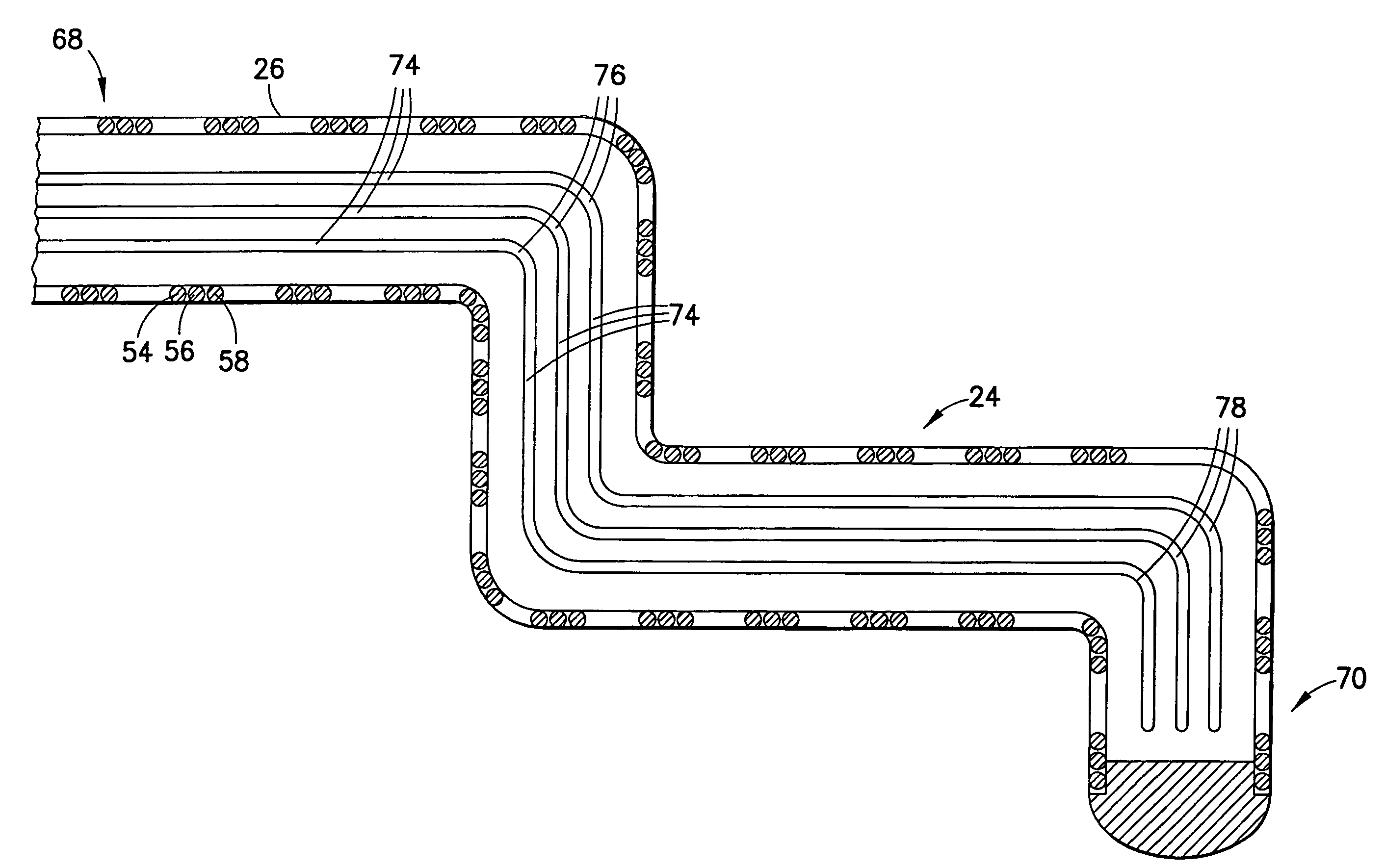
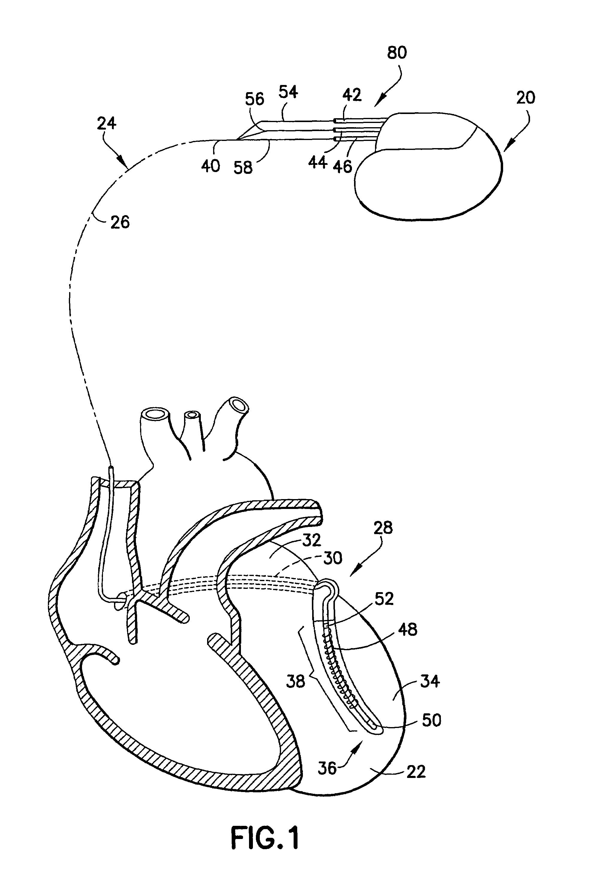
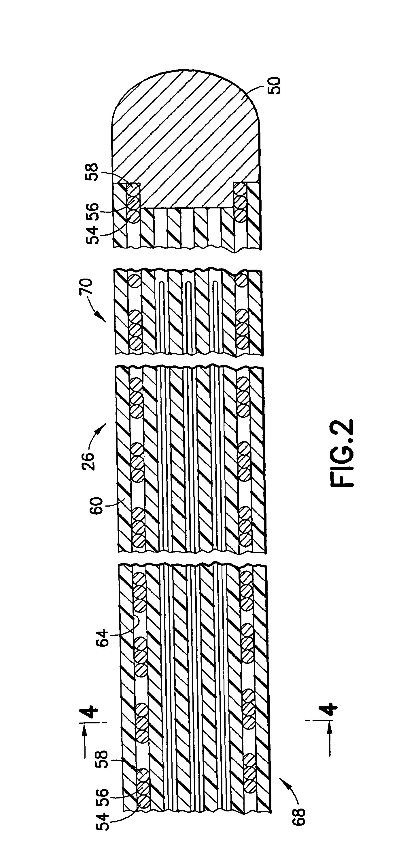
[0021]As shown in FIG. 1, a stimulation device 20 is provided in electrical communication with a patient's heart 22 by way of a lead assembly 24 embodying the present invention intended for exemplary placement in the coronary sinus region 28. Lead assembly 24 provides both left ventricular pacing and defibrillation therapy. Designed for placement in the coronary sinus region of the heart, the lead assembly 24 extends through the coronary sinus ostium 30 and adjacent to the left atrium 32 and the left ventricle 34. As used herein, the phrase “coronary sinus region” refers to the venous vasculature ...


PUM


Abstract

An implantable lead assembly for a body implantable medical system adapted to transmit electrical signals between a proximal end portion of the lead assembly and a distal end portion of the lead assembly to thereby stimulate selected body tissue includes an elongated insulative sheath of flexible resilient material having at least one longitudinally extending lumen, an electrical conductor received within the lumen of the insulative sheath and extending between a proximal end and a distal end, and at least one elongated super plastic element slidably received within the lumen of the insulative sheath, the super plastic element being bendable to configure the lead assembly to negotiate tortuous turns in the vasculature of the body. An electrical connector is coupled to the proximal end of the conductor for releasable attachment to a stimulating pulse generator and an electrode is coupled to the distal end of the conductor.

Description

FIELD OF THE INVENTION[0001]The present invention relates generally to lead assemblies for connecting implantable medical devices with selected body tissue to be stimulated by such devices and, more particularly, to such lead assemblies which are capable of negotiating tortuous turns in the vasculature of the body.BACKGROUND OF THE INVENTION[0002]Implantable cardiac stimulation devices are well known in the art. Such devices may include, for example, implantable cardiac pacemakers and defibrillators. The devices are generally implanted in a pectoral region of the chest beneath the skin of a patient within what is known as a subcutaneous pocket. The implantable devices generally function in association with one or more electrode carrying leads which are implanted within the heart. The electrodes are usually positioned within the right side of the heart, either within the right ventricle or right atrium, or both, for making electrical contact with their respective heart chamber. Condu...

Claims


Application Information

Patent Timeline
Patent Type & Authority Patents(United States)
IPC IPC(8): A61N1/05
CPCA61N1/056A61N2001/0585A61N1/0563
Inventor KROLL, MARK W.HELLAND, JOHN R.CHITRE, YOUGANDHYANG, MICHAEL
Owner PACESETTER INC
Why Eureka
Try Eureka