Method and system for presenting three-dimensional computer graphics images using multiple graphics processing units

a computer graphics and processing unit technology, applied in the field of computer graphics technology, can solve the problems of affecting the response time of the system to a user's input, the speed at which each frame is rendered is limited to the rendering rate, and the system can be delayed, so as to achieve scalable geometrically specific textures, transparent to the application program, and the effect of scaling with resp

Inactive Publication Date: 2008-07-29
MORGAN STANLEY +1
View PDF41 Cites 26 Cited by
  • Summary
  • Abstract
  • Description
  • Claims
  • Application Information

AI Technical Summary

Benefits of technology

[0015]Each GPU renders an image for the entire screen. The resultant image data that are output by the GPUs are combined using one or more image combiners to produce a final image. The image combiners can be cascaded to an arbitrary degree to achieve scalability. Each image combiner accepts the outputs of two neighboring subvolume GPUs. The combining operation is based on the alpha blending of the output of the frontmost GPUs over the output of the rearmost GPUs. Frontmost and rearmost positions are determined for each frame by the relationship between the subvolumes and the viewing position in three-dimensional space. The output of a single image combiner stage represents the image produced by the combined subvolumes and is used as the input to the next image combiner stage where it is matched with a similarly received output from a neighboring image combiner such that a scalable tree of image combiners can be configured. Where the number of GPUs to be combined exceeds a multiple of the number of GPU inputs a combiner can receive, remaining GPUs can bypass first stage combining and directly input image combiners at the next stage. The number of subvolumes does not have to be the same in each of the three dimensions nor do the dimensions of the subvolumes need to be equal in each of the three dimensions. Image combiners can be aggregated into more than two input units as desired.
[0016]The invention has the feature of decomposing the volume containing the scene to be viewed. The invention has the additional feature of providing an array of GPUs to perform the rendering operations. The invention has the additional advantage of scaling geometrically specific texture without the need for replication across all GPUs. The invention has the further advantage of being scalable with respect to the number of GPUs and image combiners that can be used. The invention has yet another advantage of being transparent to the application program. The program need not be modified to take advantage of the architecture described above or the scalability thereof.

Problems solved by technology

Time domain composition has the disadvantage of having each GPU render an entire frame.
Thus, the speed at which each frame is rendered is limited to the rendering rate of a single GPU.
While multiple GPUs enable a higher frame rate, a delay can be imparted in the response time of the system to a user's input.
With large data sets another problem is that each GPU must be able to access all of the data.
This requires either maintaining multiple copies of large data sets or possible conflicts in accessing the single copy.
Screen space composition has a similar problem with large data sets since each GPU must examine the entire data base to determine which graphic elements fall within its part of the screen.
These problems can become intractable as commercial graphics chips become limited by their ability to access data rather than by their ability to render graphic elements.
Use of this method is inhibited by the fact that the commodity graphic parts do not output the depth values, which are internally generated.
This method also prevents the application of some features, such as antialiasing or transparency, which require more information per pixel than just color and depth.

Method used


Image

  • Method and system for presenting three-dimensional computer graphics images using multiple graphics processing units
  • Method and system for presenting three-dimensional computer graphics images using multiple graphics processing units
  • Method and system for presenting three-dimensional computer graphics images using multiple graphics processing units

Examples


Embodiment Construction

[0027]Nomenclature

[0028]The present invention provides a method and system for presenting three-dimensional computer graphics images using multiple graphics processing units. The following section defines several terms that occur frequently throughout the application.

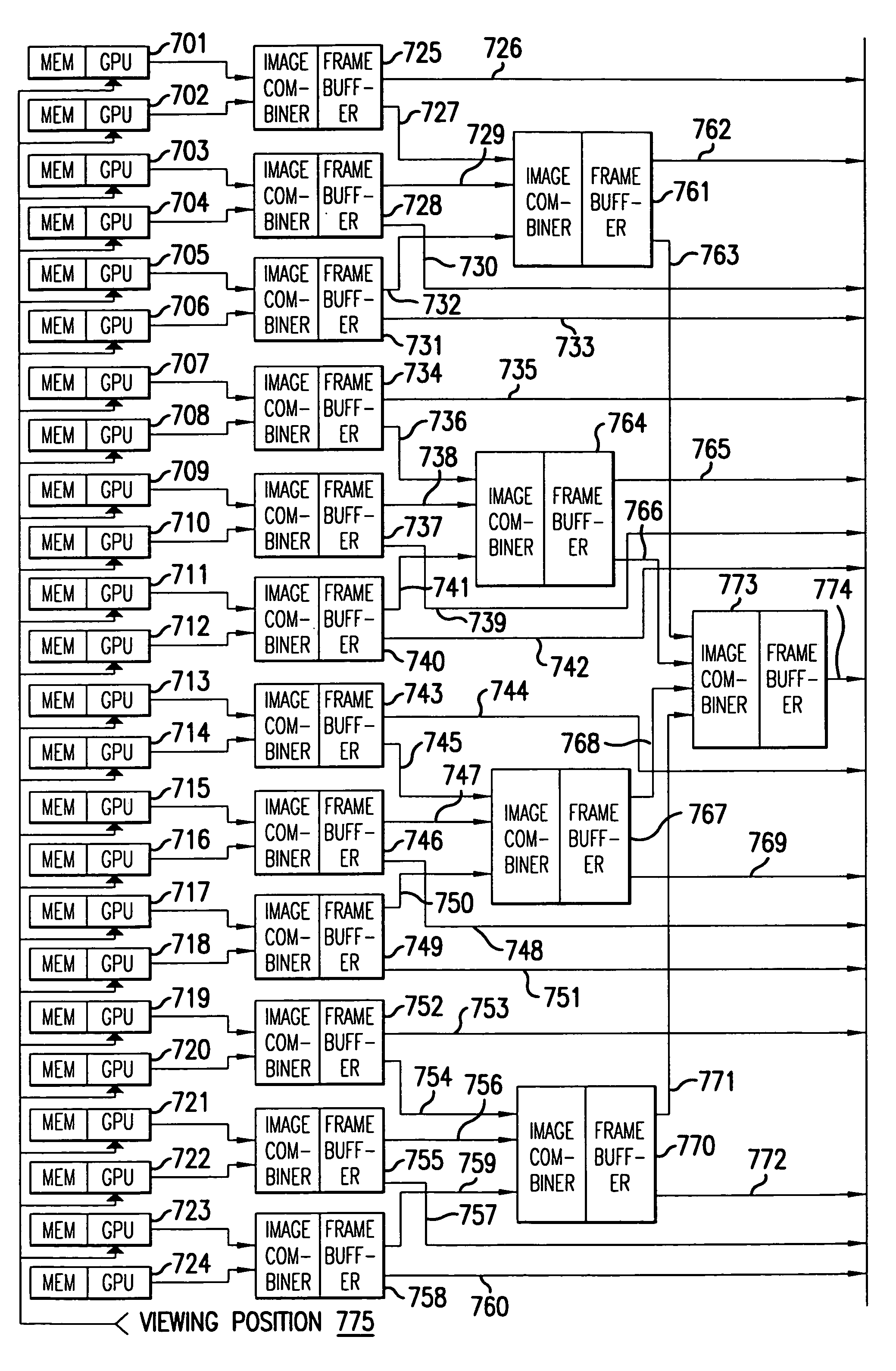
[0029]Graphics Processing Unit (GPU).

[0030]This refers to a device for rendering an image on the basis of received information, such as graphics primitives and texture data. The output of a GPU is rendered three-dimensional computer graphics data.

[0031]Image Combiner.

[0032]This refers to a device which takes the output of two or more sources of rendered three-dimensional computer graphics data and combines them. The combination process can take into account colors, opacity, and the relative depth of objects in a scene. The inputs to a combiner can come from a GPU or from another combiner. The output is rendered three-dimensional computer graphics data that is dependent on (i.e., a combination of) the inputs.

[0033]Memory...


PUM


Abstract

The present invention provides a method and system for presenting three-dimensional computer graphics images using multiple graphics processing units. The dimensions of the scene to be rendered are bounded by a rectangular volume decomposed into rectangular subvolumes. Vertices of graphics primitives are compared with subvolume boundaries to determine to which subvolume a graphics primitive should be assigned. A GPU is assigned to each subvolume to render the graphics data that lies within it. A viewing position point is determined and communicated to each GPU. Rendered graphics data from each GPU are ordered based upon the viewing position Outputs of the individual GPUs are combined by blending within an image combiners. Outputs of image combiners can be presented for viewing or further combined in a subsequent stage image combiner.

Description

[0001]This application claims the benefit of U.S. Provisional Application No. 60 / 219,006, filed Jul. 18, 2000.BACKGROUND OF THE INVENTION[0002]1. Field of the Invention[0003]The present invention relates to computer graphics technology.[0004]2. Related Art[0005]As with any type of information processing, computer graphics rendering as used for viewing a static data base has long been the subject of attempts to improve performance. Since the commoditization of computer graphic processing chips for personal computers, one method that has become particularly attractive is to use multiple numbers of these powerful (yet inexpensive) graphic processing units (GPUs) to render a single scene. Although in the archetypical rendering application, the graphic data move from frame to frame under the user's interactive control, a significant number of graphic applications can be characterized as “viewers”.[0006]In these applications, the data have been pregenerated such that their three-dimension...

Claims


Application Information

Patent Timeline
Patent Type & Authority Patents(United States)
IPC IPC(8): G06F15/16G06T17/00G06T15/00
CPCG06T15/00
Inventor FORAN, JAMES L
Owner MORGAN STANLEY
Why Eureka
Try Eureka