Reconfigurable optical filter

a technology of optical filters and configurations, applied in the field of optical filters, can solve the problems of inability to adapt to the specifications, inability to provide the same amplification for all wavelengths, and inability to adapt to the original parameters of the various components of the optical system, etc., and achieve the effect of increasing the susceptibility to second-order non-linearity and long response time for tuning the filter

Active Publication Date: 2008-07-29
RPX CORP
View PDF6 Cites 4 Cited by
  • Summary
  • Abstract
  • Description
  • Claims
  • Application Information

AI Technical Summary

Benefits of technology

[0018]Those prior art tunable filters necessitate external control systems, which are often massive. Those solutions are bulky and generally have a long response time for tuning the filter.
[0019]Incidentally, research is currently being carried out into inducing non-linear effects in a waveguide by a poling method, in order to be able to modify the refractive index of the waveguide dynamically afterwards. The poling method consists in creating, within the material whose refractive index is to be modified, a direction and a preferential sense in that direction that increase susceptibility to second order non-linearity.

Problems solved by technology

The optical amplifiers generally do not provide the same amplification for all wavelengths of the signals transmitted on the various channels of the same transmission line.
Unfortunately, optical systems often evolve with time and it is not rare for the parameters of an optical component such as a dispersion compensator gain equalizer to cease to be adapted to the specifications of real transmission systems.
The original parameters of the various components of the optical system then become inappropriate.
However, if the channels are close together in the spectrum (≦50 GHz), it becomes difficult to place the filter between two channels without modifying the transmissions.

Method used


Image

  • Reconfigurable optical filter
  • Reconfigurable optical filter

Examples


Embodiment Construction

[0037]In one embodiment, the method further comprises a step of optically writing a Bragg grating in the guide portion containing the nanoparticles.

[0038]Depending on the application, the nanoparticles having a high 3rd order dielectric susceptibility (χ3) are distributed continuously or periodically over the guide portion.

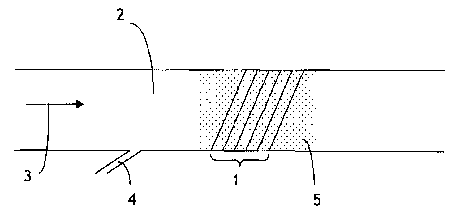
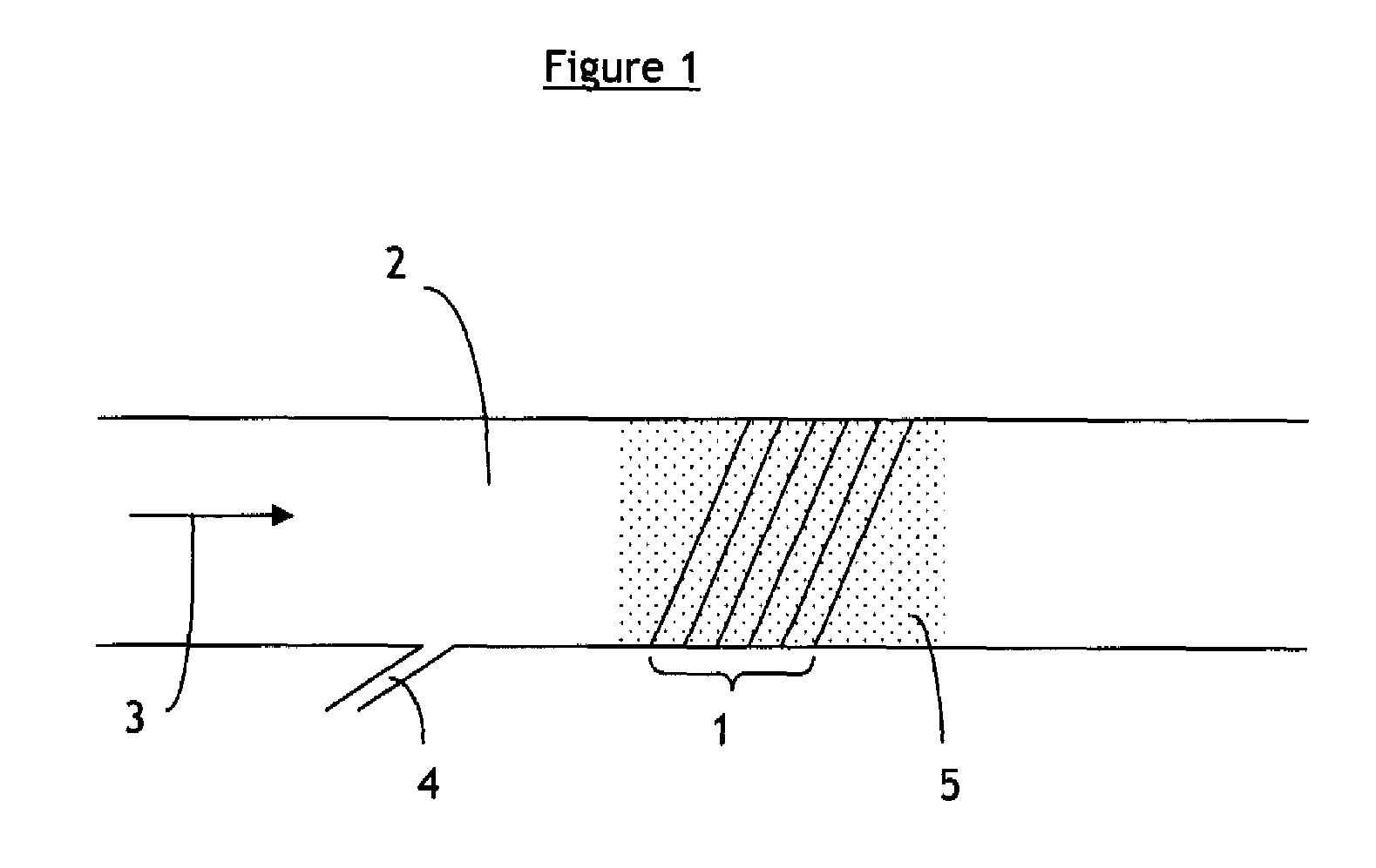
[0039]FIG. 1 shows a tunable optical filter according to an exemplary embodiment of the present invention. The tunable optical filter includes an index grating 1 made up of a refractive index variation in an optical waveguide 2. The waveguide 2 defines a longitudinal direction of propagation 3 of an incident optical signal. At least one optical parameter of the index grating can be tuned by application of an optical control signal 4 coupled into the guide 2 and propagating longitudinally in the guide 2.

[0040]The optical waveguide 2 contains semiconductor nanoparticules 5 that are continuously or periodically distributed over the guide portion 2. The nanoparticules...


PUM

PropertyMeasurementUnit
refractive indexaaaaaaaaaa

Abstract

A tunable optical filter comprising an index grating produced in a waveguide defining a longitudinal direction of propagation of an incident optical signal, said grating being defined by a plurality of optical parameters, is characterized in that the optical guide contains semiconductor nanoparticles and in that the index grating is made up of a refractive index variation in the guide that is at least partly induced by a Kerr effect linked to the 3rd order dielectric susceptibility (χ3) of said nanoparticles, at least one of said parameters of said index grating being modified by application of an optical control signal coupled into the guide and propagating longitudinally in said guide.

Description

CROSS-REFERENCE TO RELATED APPLICATION[0001]This application claims priority from French Patent Application No. 0304911, filed in the French Patent Office on Apr. 22, 2003, the disclosure of which is incorporated herein by reference in its entirety.BACKGROUND OF THE INVENTION[0002]1. Field of the Invention[0003]The field of the present invention is that of optical filters disposed in optical waveguides.[0004]2. Description of the Related Art[0005]Optical filters, such as Bragg gratings written optically into optical waveguides, are finding increasingly important applications in optical systems, in which they are used for applications such as wavelength selection, gain equalization, and chromatic dispersion compensation, for example.[0006]A waveguide conventionally comprises an optical core, the function of which is to transmit and possibly to amplify an optical signal, surrounded by optical cladding, the function of which is to confine the optical signal within the core. To this end...

Claims


Application Information

Patent Timeline
Patent Type & Authority Patents(United States)
IPC IPC(8): G02F1/03G02B6/34G02F1/07G02F1/35G02F1/355G02F1/365
CPCB82Y20/00G02F1/3515G02F1/355G02F2203/055G02F2201/307G02F2202/36G02F1/365
Inventor RIANT, ISABELLEBELOUET, CHRISTIAN
Owner RPX CORP
Why Eureka
Try Eureka