Semiconductor spectroscopy system

a spectroscopy system and semiconductor technology, applied in the field of semiconductor spectroscopy systems, can solve the problems of high power consumption of systems, inefficient systems, and excessive sample heating

Active Publication Date: 2008-07-29
EXCELITAS TECH
View PDF9 Cites 9 Cited by
  • Summary
  • Abstract
  • Description
  • Claims
  • Application Information

AI Technical Summary

Problems solved by technology

Sometimes, this can result in excessive sample heating.
Also high power is generated at the optical source, most of it being unused, making the system inefficient.
While often powerful, these systems also have high power consumptions.

Method used


Image

  • Semiconductor spectroscopy system
  • Semiconductor spectroscopy system
  • Semiconductor spectroscopy system

Examples


Embodiment Construction

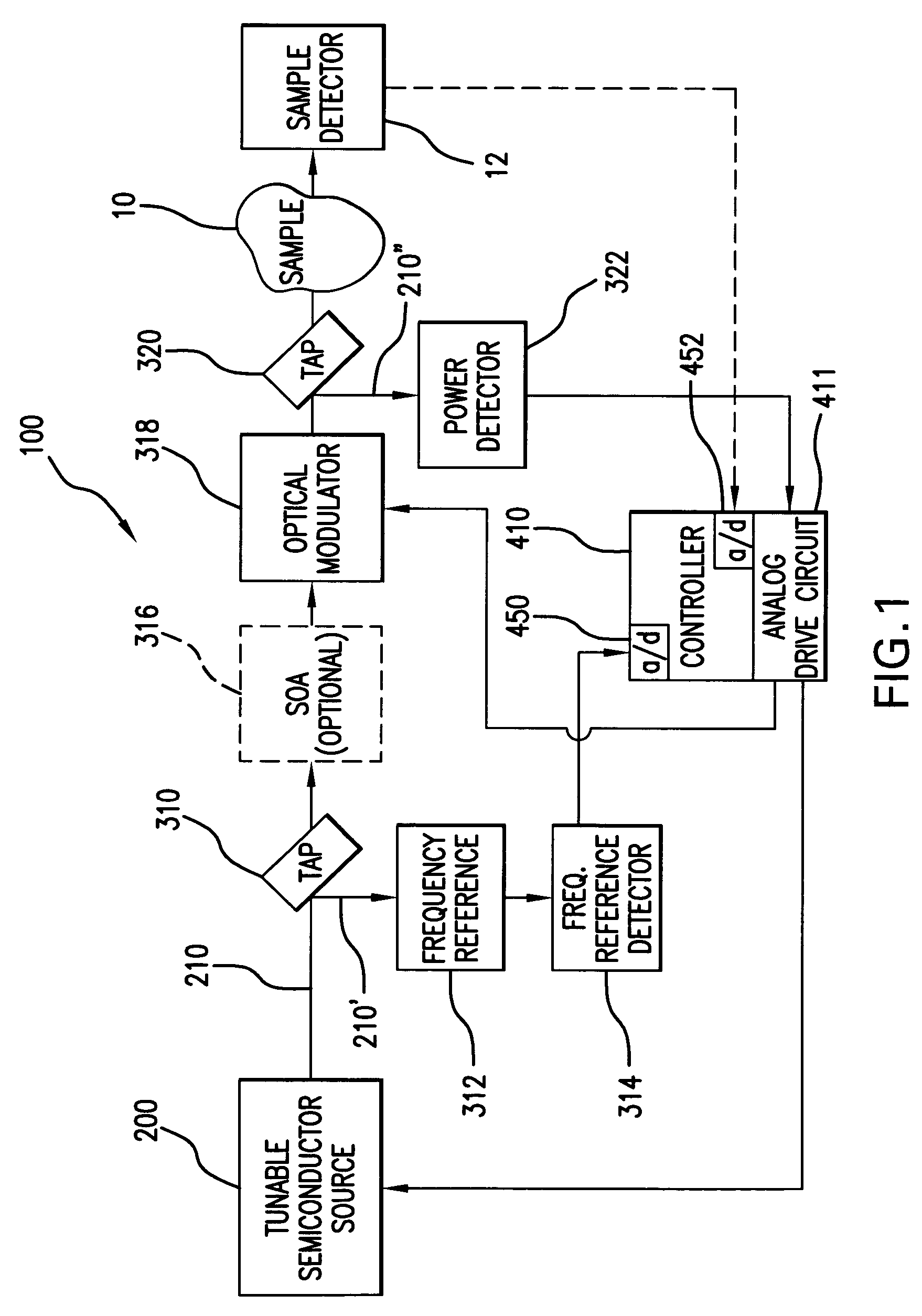
[0031]FIG. 1 shows a semiconductor source spectroscopy system 100, which has been constructed according to the principles of the present invention.

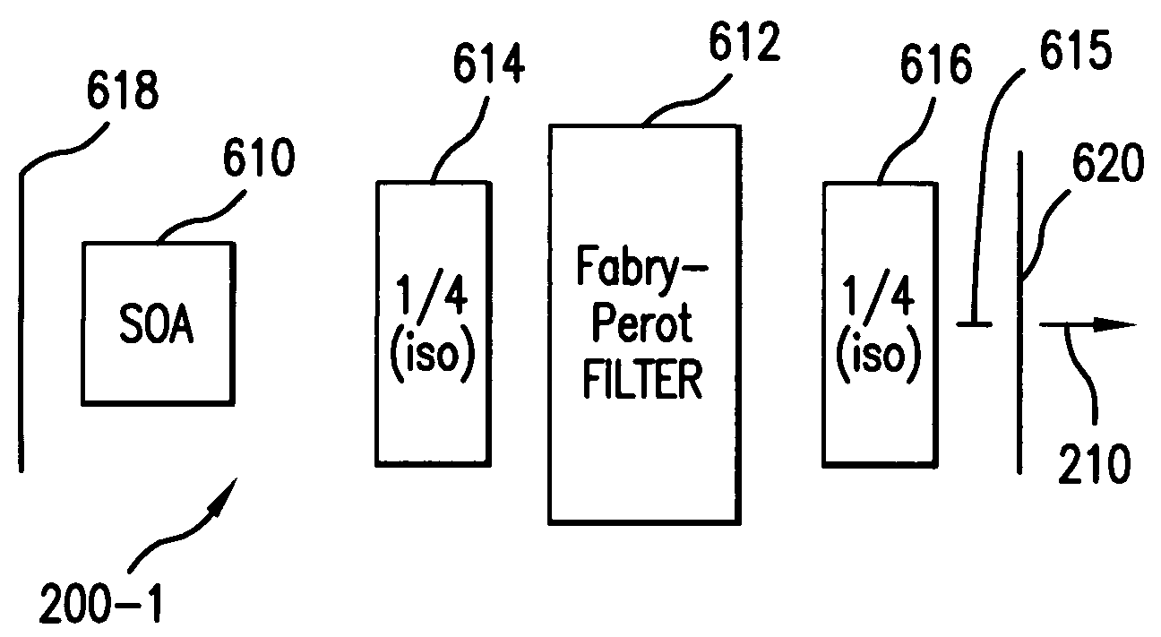
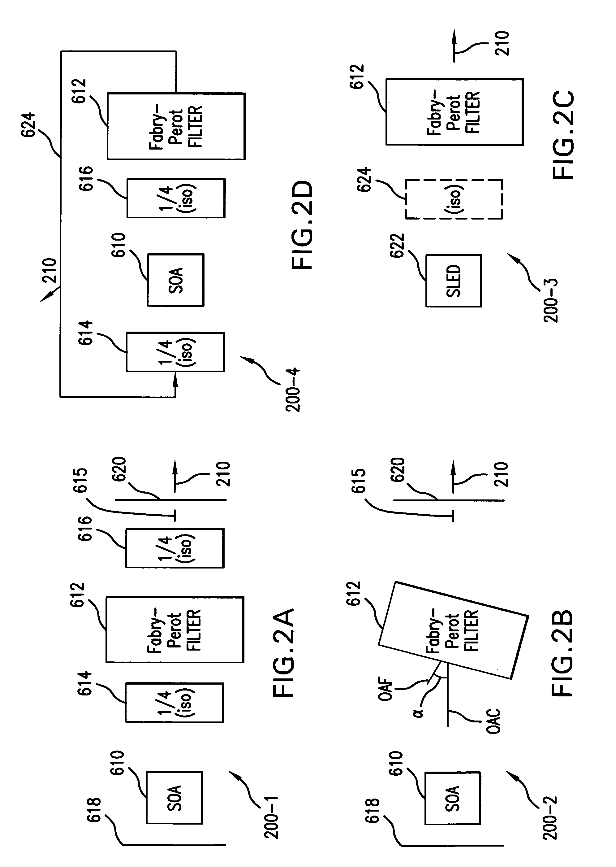
[0032]Generally, the spectroscopy system 100 comprises a tunable semiconductor source 200. This generates a tunable optical signal 210.

[0033]In one example, the tunable signal 210 is transmitted to a frequency reference tap 310 that diverts a portion of the tunable optical signal 210′ to an optical frequency or wavelength reference 312. In one example, this optical reference is a fixed cavity etalon that provides a number of spectral passbands located within and / or spectrally adjacent the scan band of the system 100. Optionally, a post-amplifier tracking tunable optical filter is sometimes used to filter out or remove any optical noise contributed by the amplifier.

[0034]The signal 210′ that is transmitted through the optical reference 312 is then detected by a frequency reference detector 314. The output of the frequency reference detecto...


PUM


Abstract

An optical power control system for a semiconductor source spectroscopy system controls power fluctuations in the tunable signal from the spectroscopy system and thus improves the noise performance of the system. This general solution has advantages relative to other systems that simply detect reference power levels during the scan and then correct the detected signal after interaction with the sample by reducing the requirements for coordinating the operation of the sample detectors and power or reference detectors. The spectroscopy system comprises a semiconductor source and a tunable filter. The combination of the semiconductor source and tunable signal illuminate a sample with a tunable signal, being tunable over a scan band. The power control system comprises an amplitude detector system for detecting the power of the tunable optical signal and power control system for regulating the amplitude of the tunable optical signal in response to its detected power.

Description

RELATED APPLICATIONS[0001]This application is related to application Ser. No. 10 / 953,046, filed on Sep. 29, 2004, now U.S. Published Application Publication No. US 2006 / 0065834-A1, published on Mar. 30, 2006 and Ser. No. 10 / 953,043, filed on Sep. 29, 2004, now U.S. Published Application Publication No. US 2006 / 0072632 A1, published on Apr. 6, 2006, both applications, by Flanders, et al.BACKGROUND OF THE INVENTION[0002]Most spectroscopy systems fall into one of two categories. They can be tunable source systems that generate a tunable optical signal that is scanned over a scan band. A detector is then used to detect the tunable optical signal after interaction with the sample. The time response of the detector corresponds to the spectral response of the sample. Such systems are typically referred to as pre-dispersive. Alternatively, a tunable detector system can be used. In this case, a broadband signal is used to illuminate the sample. Then, a bandpass filter is tuned over the scan ...

Claims


Application Information

Patent Timeline
Patent Type & Authority Patents(United States)
IPC IPC(8): H01S3/10
CPCG01J1/4257H01S5/141G01J3/0213G01J3/0256G01J3/10G01J3/26G01J3/433G01N21/39G01J3/02G01J2003/2866G01N2021/391G01N2021/399G01N2201/08H01S3/08013H01S3/083H01S5/005H01S5/0064H01S5/02252H01S5/02326
Inventor FLANDERS, DALE C.MA, XINFAATIA, WALID A.
Owner EXCELITAS TECH
Why Eureka
Try Eureka