

X-ray microscope with microfocus source and Wolter condenser
- Summary
- Abstract
- Description
- Claims
- Application Information
AI Technical Summary
Benefits of technology
Problems solved by technology
Method used
Image

Examples
Embodiment Construction
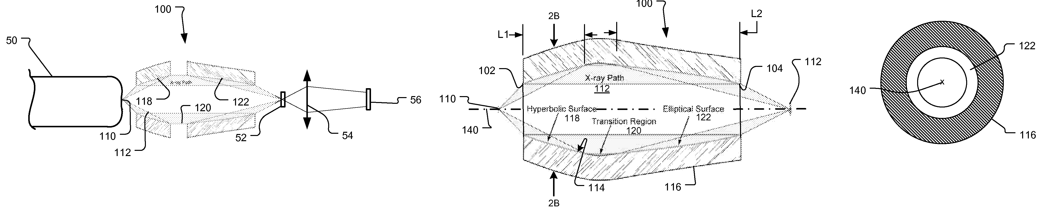
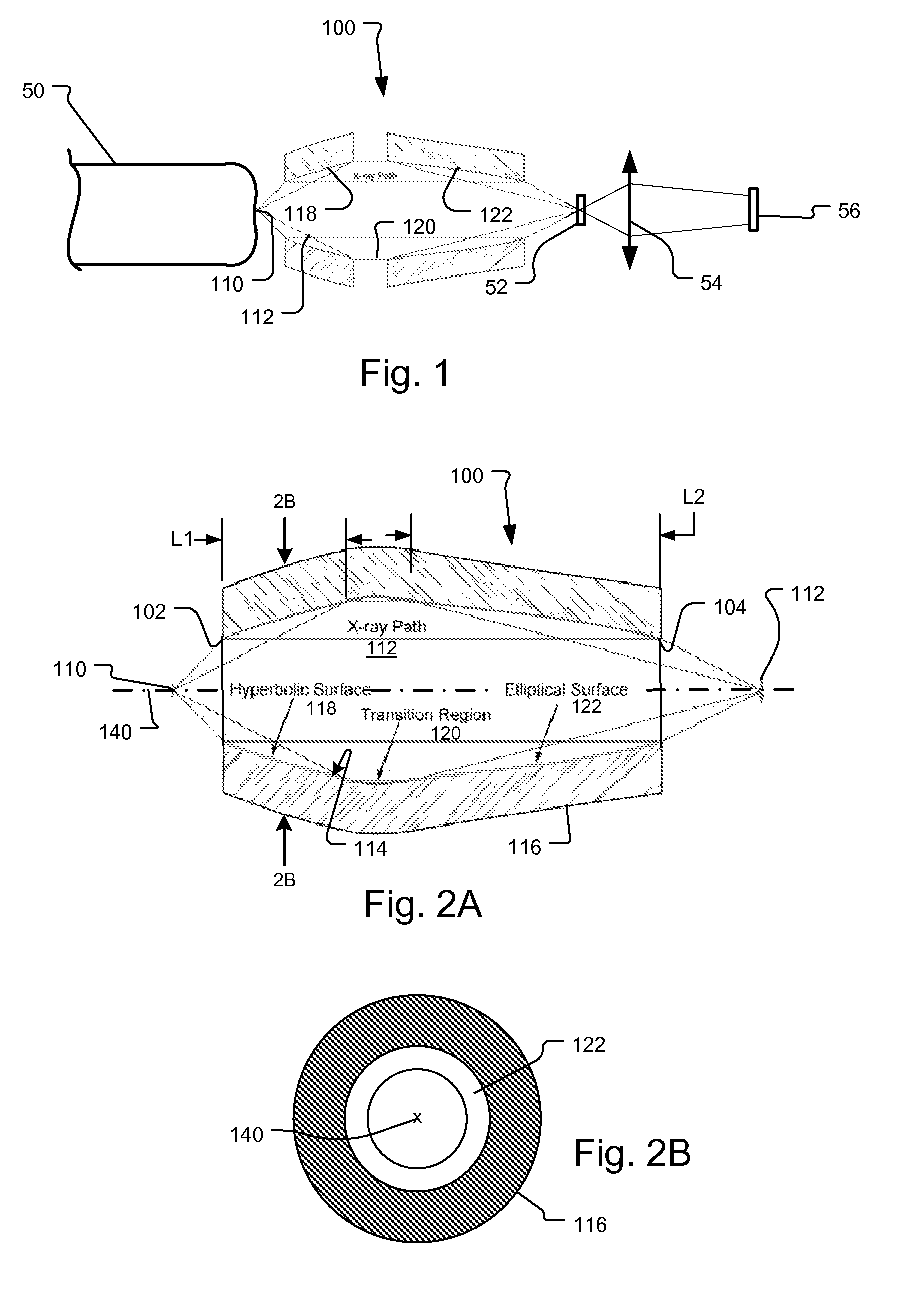
[0018]The problem that arises when using such microfocus sources in x-ray microscopes concerns the microscopes' field of view, which are usually much larger than the microfocus source's size. For example, for an x-ray microscope with 25 nanometer (nm) resolution and 1000×1000 detector pixels, a desirable field of view is about 10 micrometers (μm) assuming a 2.5 times sampling per resolution element. For a one micrometer diameter microfocus x-ray source, the condenser needs to magnify the source by more than 10 times to illuminate this field of view.
[0019]Currently, the most efficient x-ray condensers for x-ray microscopes are suitably configured mirrors operating at grazing incidence. For grazing incidence angles smaller than the critical angle for total reflection, X-ray reflectivity for most mirror materials is typically better than 85% for multi kilo electron-Volts (keV) x-rays.
[0020]In x-ray microscopes using synchrotron x-ray sources, common focusing mirrors include torroidal m...
PUM
 Abstract
Description
Claims
Application Information