Projection type image display unit

a video display and projection type technology, applied in the field of projection type video displays, can solve the problems of reducing image quality, offensive ear noise produced by suction and exhaust sound when a projector is used, etc., and achieve the effect of reducing the blowing capability of the fan and reducing the ventilation of generated ozone outward the video display

Inactive Publication Date: 2008-08-05
SANYO ELECTRIC CO LTD
View PDF19 Cites 16 Cited by
  • Summary
  • Abstract
  • Description
  • Claims
  • Application Information

AI Technical Summary

Benefits of technology

[0006]With the above-described configuration, the ion wind generator allows the air flow to be occurred by electrically moving an ionized air, and the like. As a result, different from blowing by the rotation of a fan, no rotation noise is produced, so that, when air is taken in or exhausted, an almost soundless state is made possible. Moreover, even if ozone is generated by the ionization, the ozone is removed by the ozone removal filter.
[0008]The ion wind generator may be so provided as to take air outside of the video display into the video display. Furthermore, in this configuration, if a mechanism in which dust is caught by the electrode on the other side of the ion wind generator is utilized, the ion wind generator becomes a dust removal device. When the ion wind generator is used as the dust removal device and used together with a fan, dust removal is possible without reducing a blowing capability of the fan. Moreover, the ozone is removed by the ozone removal filter.
[0009]It is preferable that a projection type video display comprises a sensor for detecting temperature or ambient temperature of the ozone removal filter and a control means for turning on the ion wind generator when the temperature is equal to or higher than predetermined temperature and turning off the ion wind generator when the temperature is lower than the predetermined temperature. With this configuration, since it is possible to send an air after reaching a stage that an ozone removal capability of the ozone removal filter is fully demonstrated, ventilation of generated ozone outward the video display is reduced as much as possible.
[0010]Moreover, it is desirable that the ion wind generator is turned on or off when a predetermined time period has passed after the light source was turned on or off. Also in this configuration, it is possible to send an air after reaching the stage that the ozone removal capability of the ozone removal filter is fully demonstrated, the ventilation of the generated ozone outward the video display is reduced as much as possible.

Problems solved by technology

However, in a suction and exhaust mechanism using motor driving, noises are produced due to suction and exhaust sound by rotating sound of a motor and hissing sound of a fan.
As a result, the noise produced by the suction and exhaust sound is offensive to the ear when a projector is used.
However, if dust in the air adheres to the light valve, a quality of image is lowered, so that a filter is needed.

Method used


Image

  • Projection type image display unit
  • Projection type image display unit
  • Projection type image display unit

Examples


embodiment 1

[0016]Hereinafter, a projection type video display according to an embodiment of the present invention will be described referring to FIGS. 1 to 3.

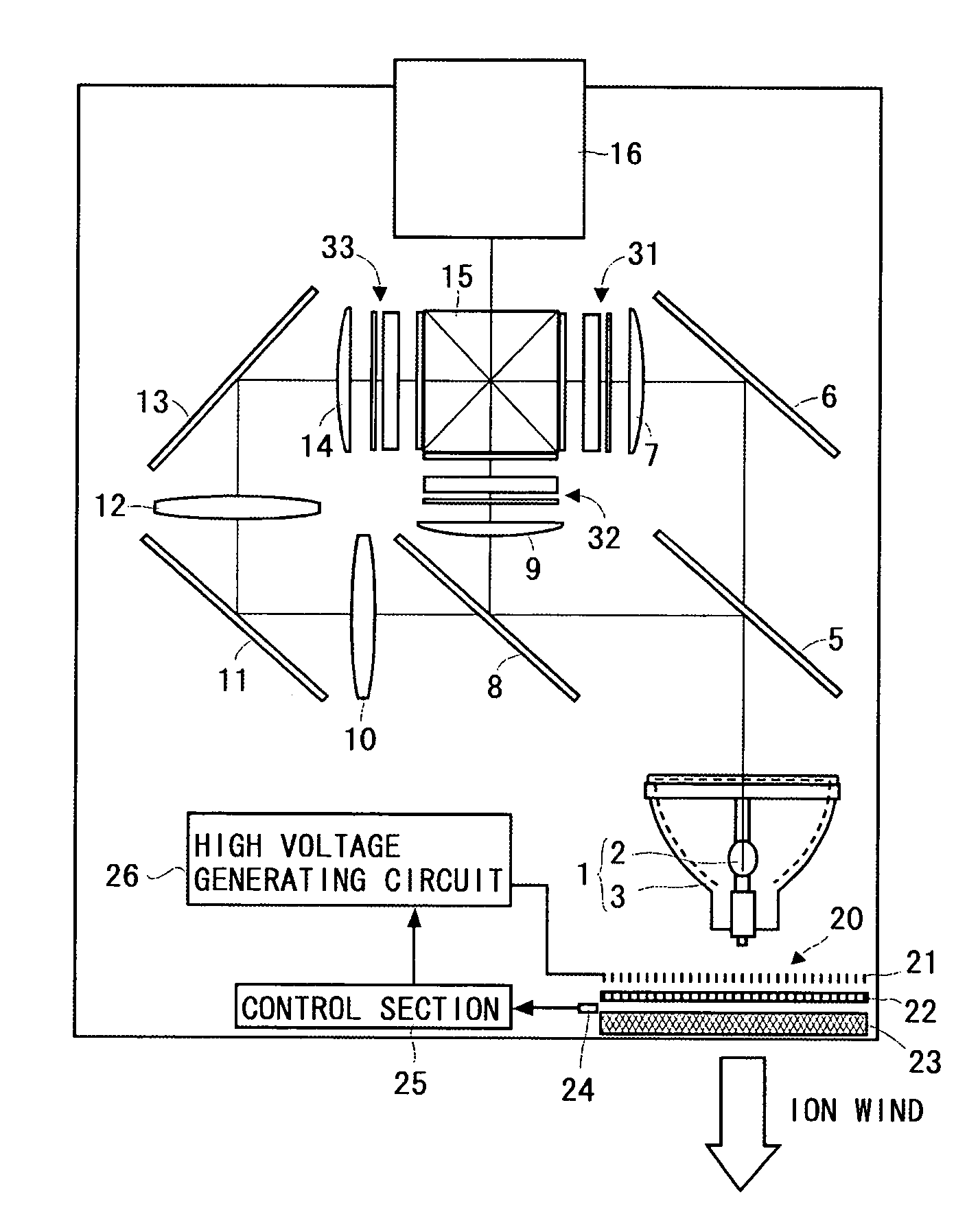
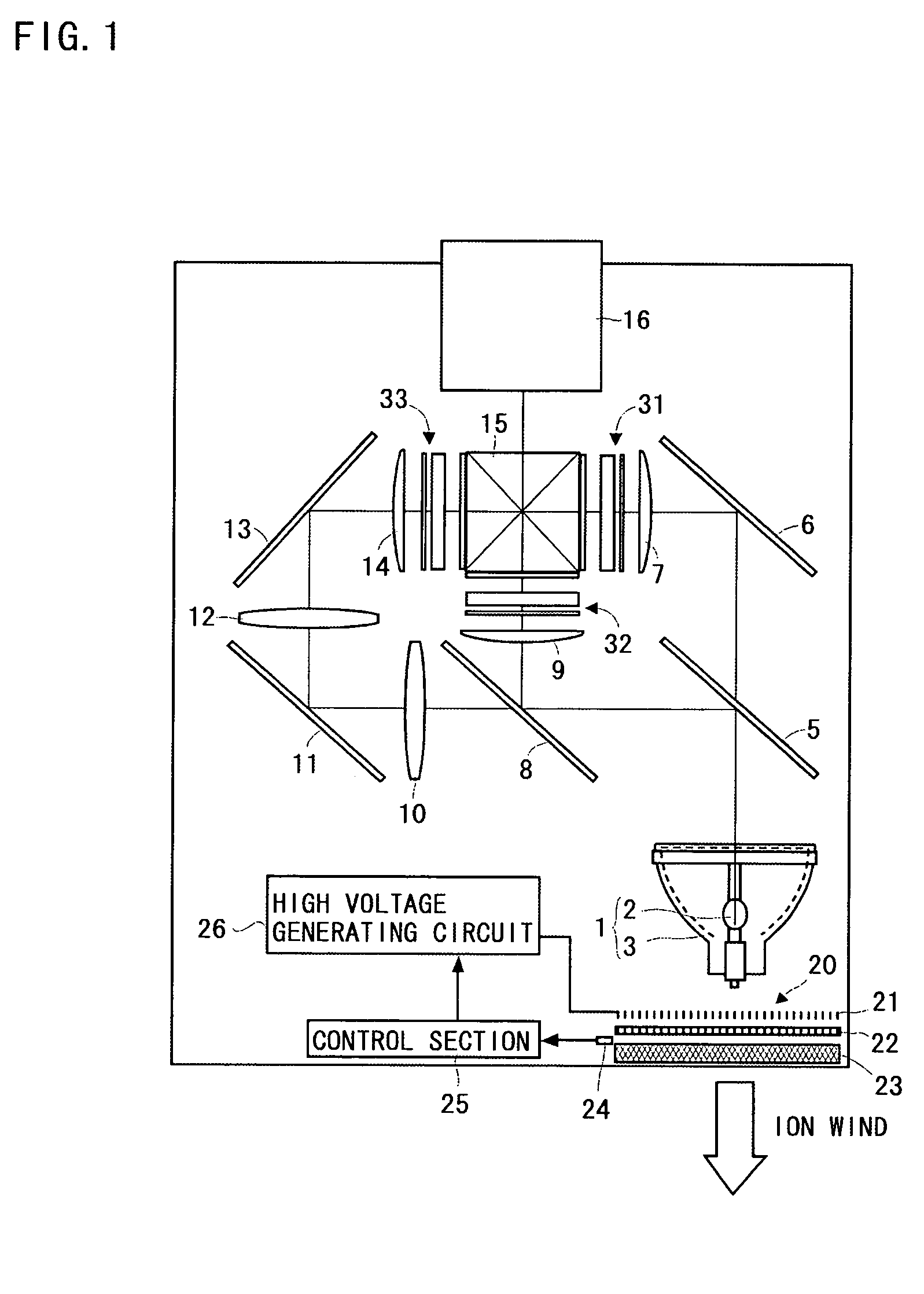
[0017]FIG. 1 is a diagram showing an optical system of a three-panel color liquid crystal projector. A light emitter 2 of a light source 1 is composed of an ultra-high pressure mercury lamp, a metal halide lamp, a xenon lamp, and the like, and light irradiated therefrom is emitted after being changed into parallel light by a parabolic reflector 3, for example.

[0018]A first dichroic mirror 5 transmits light in a red wavelength band, while reflecting light in a cyan (green+blue) wavelength band. The light in the red wavelength band which passes through the first dichroic mirror 5 is reflected by a reflection mirror 6 so that its optical path is changed. The red light which is reflected by the reflection mirror 6 is optically modulated by passing through a transmission type liquid crystal light valve for red light 31 through a condenser lens...

embodiment 2

[0028]Hereinafter, a fan 200 (hereinafter, referred to as a dust collection wind fan 200) with the ion wind generator provided in the projection type video display of an embodiment of the present invention will be described with referring to FIGS. 4 to 5.

[0029]FIG. 4 is a perspective view (partly transparent) showing the dust collection wind fan 200. The dust collection wind fan 200 comprises a dust collection portion (ion wind generator) and a wind fan portion (sirocco fan).

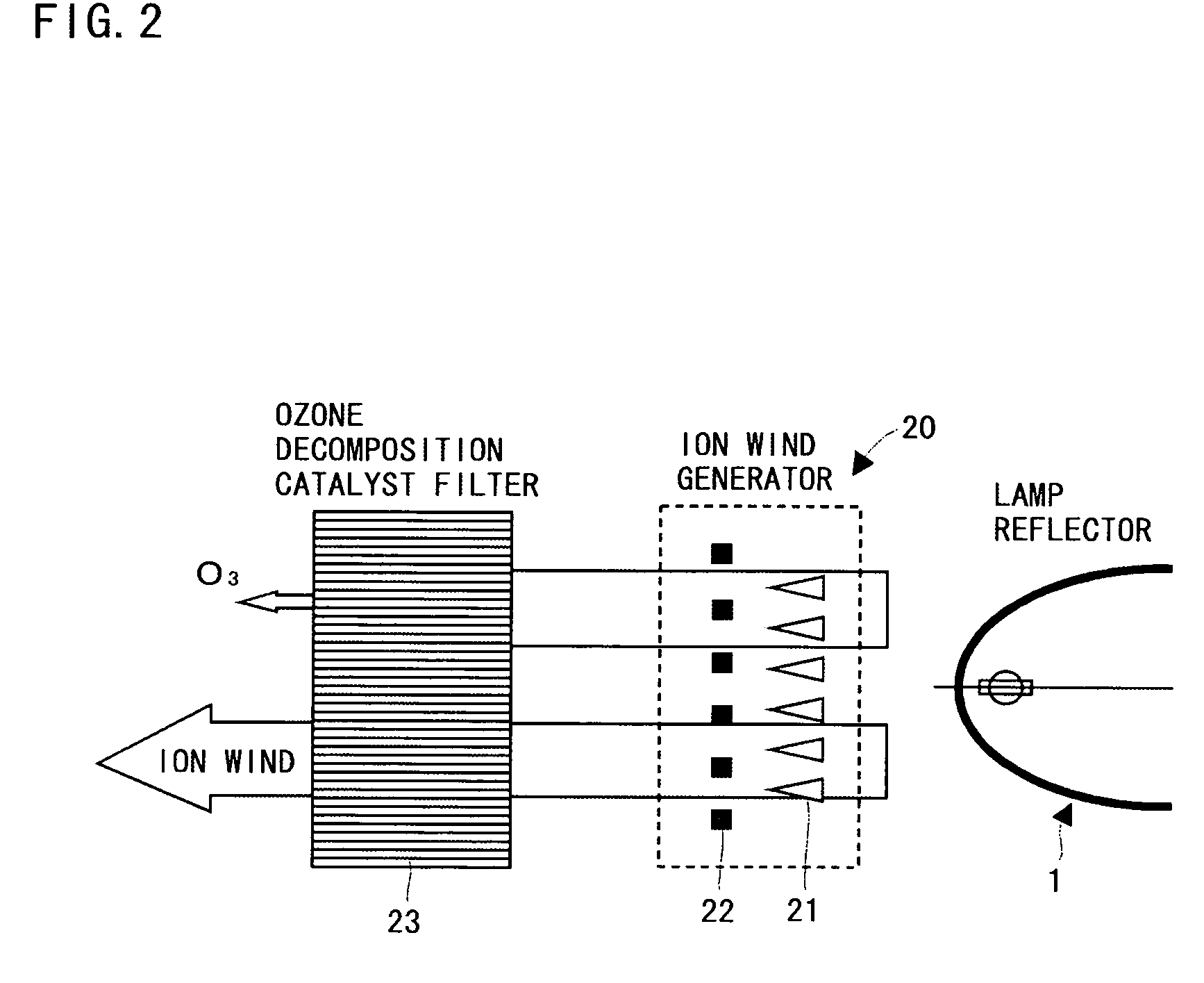
[0030]The dust collection wind fan 200 is constructed by arranging needle electrodes 221, a first mesh electrode 222A and a second mesh electrode 222B, and an ozone decomposition catalyst filter 223 in a rectangular cylinder in the above-mentioned order in the direction of air flow. The dust collection wind fan 200 negatively ionizes air, dust, and the like, by corona discharges using a multiplicity of negative-side needle electrodes 221, and generates air flow by drawing the negatively-ionized air, dust, and th...


PUM

PropertyMeasurementUnit
temperatureaaaaaaaaaa
lengthaaaaaaaaaa
temperatureaaaaaaaaaa

Abstract

An ion wind generator is arranged in the vicinity of a light source. The ion wind generator allows an air flow by negatively ionizing air by corona discharges using negative side needle electrodes, and drawing the negatively-ionized air using a ground side mesh electrode. High-temperature air surrounding the light source is drawn by the air flow and exhausted from an exhaust port at a rear side of a casing. An ozone decomposition catalyst filter is provided in the exhaust port. Ozone (O3) is generated by the corona discharges in the ion wind generator. However, the ozone is decomposed by passing through the ozone decomposition catalyst filter provided at the exhaust port.

Description

TECHNICAL FIELD[0001]The present invention relates to a projection type video display such as a liquid crystal projector, and the like.PRIOR ART[0002]A projection type video display is so configured that light emitted from a light source is modulated by a light valve such as a liquid crystal panel, and the like, and projected, so that it is necessary to comprise a high-luminance light source. Consequently, measures to prevent heat generated from the high-luminance light source itself and heat generated when light is absorbed in a light polarizer in the liquid crystal panel or various types of optical components are required. Conventionally, a projection type video display has a structure in which air is taken in and exhausted, and the heat is released from a casing by rotating a fan with a motor (see JP-A-2001-222065).[0003]However, in a suction and exhaust mechanism using motor driving, noises are produced due to suction and exhaust sound by rotating sound of a motor and hissing so...

Claims


Application Information

Patent Timeline
Patent Type & Authority Patents(United States)
IPC IPC(8): G03B21/18B03C3/41B03C3/45H04N5/74G02F1/1333G03B21/16G03B21/00H01T23/00
CPCG03B21/16H01T23/00H04N9/3144H04N9/3141H04N5/7416
Inventor ISHII, KOJIIKEDA, TAKASHIKANAYAMA, HIDEYUKIFUNAZOU, YASUOMIWA, TAKASHI
Owner SANYO ELECTRIC CO LTD
Why Eureka
Try Eureka