Interback-type substrate processing device

a substrate processing and back-type technology, applied in the direction of instruments, furniture, charge manipulation, etc., can solve the problems of large carry chamber section, difficult to meet the requirements of devices that are long to be assembled in existing production lines, and workability and efficiency problems, so as to achieve the effect of improving productivity

Inactive Publication Date: 2008-08-05
CANON ANELVA CORP
View PDF27 Cites 19 Cited by
  • Summary
  • Abstract
  • Description
  • Claims
  • Application Information

AI Technical Summary

Benefits of technology

[0018]The technological significance of the invention of the present application, which is designed in order to solve these problems, lies in the fact that it provides a substrate processing device that is able to meet the demands of a greater intricacy of the process as a whole and improvements in productivity.

Problems solved by technology

First, in inline-type substrate processing devices, when the number of processing chambers is increased in order to increase the number of processing steps, the length of the device in the direction of the tray line is lengthened by that amount. In inline-type devices, because the substrate is carried in from one side of the device and is carried out from the other side, problems of workability and efficiency arise when the length of the device is increased and the carry-in position and the collection position of the substrate are separated further. In addition, a problem arises in that it is difficult for devices that are lengthy to be assembled in existing production lines.
There are drawbacks accompanying this in that the cross-section of the carry chamber is larger and the occupied area of the device as a whole is larger.
As the carry chamber is a section that does not directly contribute to productivity, an increase in size of this section is undesirable.
In addition, when the carry chamber is enlarged, there are problems in that the scale of the pump system for pumping out the inner space is larger and more expensive.
As a result, the scale of the transfer robot is larger and more expensive and, as a result of a lengthening of the arm of the transfer robot, problems in flexibility of the arm and reduction of carry precision arise.

Method used


Image

  • Interback-type substrate processing device
  • Interback-type substrate processing device
  • Interback-type substrate processing device

Examples


Embodiment Construction

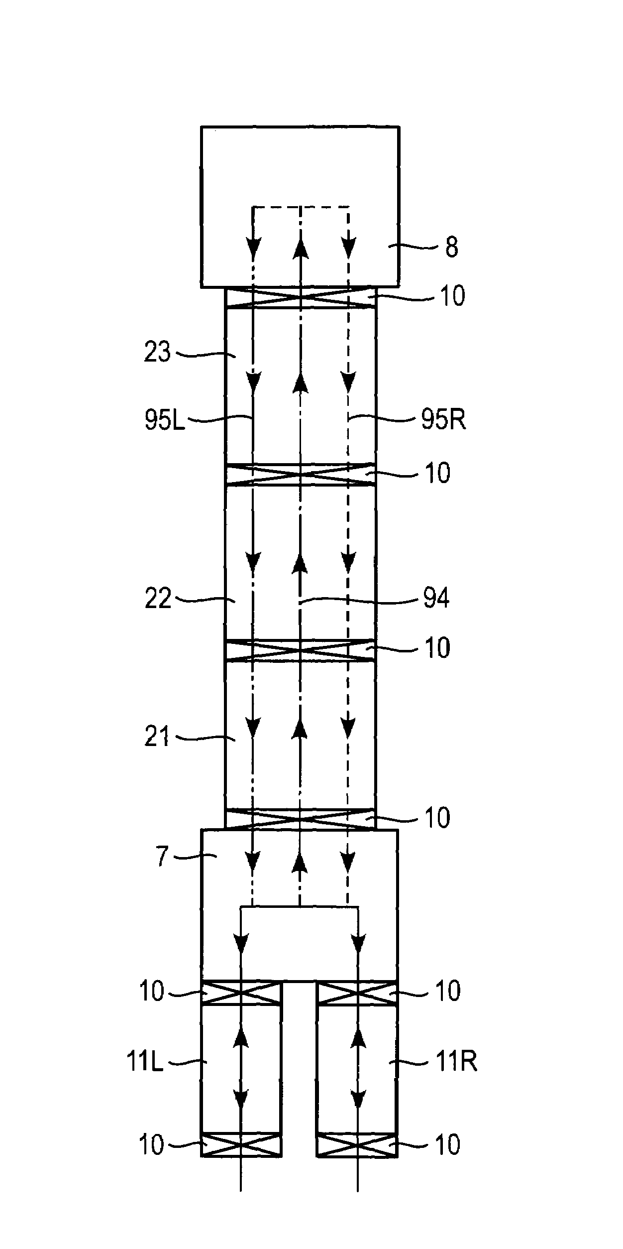
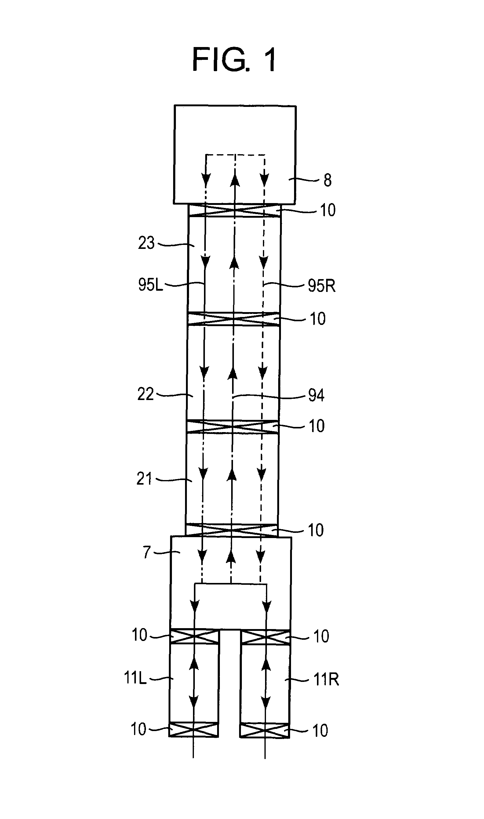
[0032]With reference to FIG. 1, a description is given of the entire configuration of a preferred embodiment of a substrate processing device of the present invention. FIG. 1 is a plane-surface schematic view of the preferred embodiment.

[0033]The substrate processing device shown in FIG. 1 is a structure in which a plurality of vacuum chambers comprising processing chambers 21, 22, 23 for administering predetermined processing to a substrate 9 therein are hermetically connected. In addition, the device comprises a carry system (not shown in the diagram) for transferring the substrate 9 in sequence to the plurality of vacuum chambers.

[0034]Two of the plurality of vacuum chambers form load-lock chambers 11L, 11R with the atmospheric side in which, at times when the substrate 9 is introduced and discharged, the substrate 9 is temporarily retained. The two load-lock chambers 11L, 11R are arranged on the same side of the system as shown in FIG. 1. Accordingly, the transfer-in and transfe...


PUM

PropertyMeasurementUnit
angleaaaaaaaaaa
angleaaaaaaaaaa
angleaaaaaaaaaa

Abstract

An interback-type device in which a substrate 9 is carried into the device from one side of the device and is inverted in the device to be carried out and returned to the same side, a plurality of vacuum processing chambers 21, 22, 23 are longitudinally-provided and hermetically connected, and a carry system which passes through these vacuum chambers for carrying the substrate along established carry lines 94, 95L, 95R is provided. The carry line includes an outward carry line 94 toward an inversion position and return carry lines 95L, 95R returning from the inversion position, and the outward line 94 and return carry lines 94, 95L, 95R are different parallel paths, and the return carry lines 95L, 95R are branched in plurality. The outward carry line 94 and return carry lines 95L, 95R are established to pass through the same three processing chambers 21, 22, 23.

Description

CROSS-REFERENCE TO RELATED APPLICATIONS[0001]The present application claims the priority of JP2000-399444, filed in Japan on Dec. 27, 2000, the entire contents of which are hereby incorporated by reference.BACKGROUND OF THE APPLICATION[0002]1. Technological Field to Which the Invention Belongs[0003]The invention of the present application relates to a substrate processing device suitable for use in the manufacture of display devices, such as liquid crystal displays.[0004]2. Discussion of Related Art[0005]In the manufacture of various display devices, such as liquid crystal displays and plasma displays, a process such as surface-processing must be administered on a plate-shaped material that forms the base of the device (hereinbelow referred to as the substrate). By way of example, in liquid crystal displays, a process to form a transparent electrode on the plate surface (surface that is not the peripheral surface) of the glass substrate is required.[0006]The substrate processing dev...

Claims


Application Information

Patent Timeline
Patent Type & Authority Patents(United States)
IPC IPC(8): H01L21/677B65G49/06B65G49/07G02F1/1333H01L21/203H01L21/205H01L21/302H01L21/3065
CPCH01L21/67742G02F1/1333
Inventor TAKAHASHI, NOBUYUKI
Owner CANON ANELVA CORP
Why Eureka
Try Eureka