Broadside-to-edge-coupling connector system

a connector system and broadside-to-edge technology, applied in the field of broadside-to-edge-coupling connector systems, electrical connector systems, can solve the problems of compromising signal integrity, unsatisfactory cross-talk, and compromising signal integrity, so as to reduce the weight of the connector, reduce the loss of insertion, and reduce the effect of constant impedan

Inactive Publication Date: 2008-08-05
FCI AMERICAS TECH LLC
View PDF64 Cites 44 Cited by
  • Summary
  • Abstract
  • Description
  • Claims
  • Application Information

AI Technical Summary

Benefits of technology

[0010]The connector system may also include novel contact configurations for reducing insertion loss and maintaining substantially constant impedance along the lengths of contacts. The use of air as the primary dielectric to insulate the contacts may result in a lower weight connector that is suitable for use in various connectors, such as a right angle ball grid array connector. Plastic or other suitable dielectric material may be used.

Problems solved by technology

Often, the signal contacts are so closely spaced that undesirable interference, or “cross-talk,” may occur between adjacent signal contacts.
Cross-talk may occur when one signal contact induces electrical interference in an adjacent signal contact due to intermingling electrical fields, thereby compromising signal integrity.
As demand for smaller devices increases, existing techniques for reducing cross-talk may no longer be desirable.
For instance, electrical shields and / or ground contacts consume valuable space within the connector, space that may otherwise be used to provide additional signal contacts and, thus, increase signal contact density.
Furthermore, the use of shields and / or ground contacts may increase connector cost and weight.

Method used


Image

  • Broadside-to-edge-coupling connector system
  • Broadside-to-edge-coupling connector system
  • Broadside-to-edge-coupling connector system

Examples


Embodiment Construction

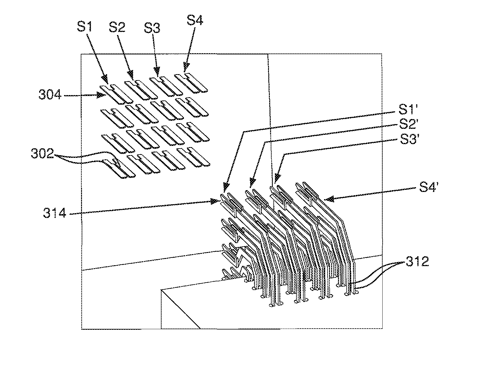
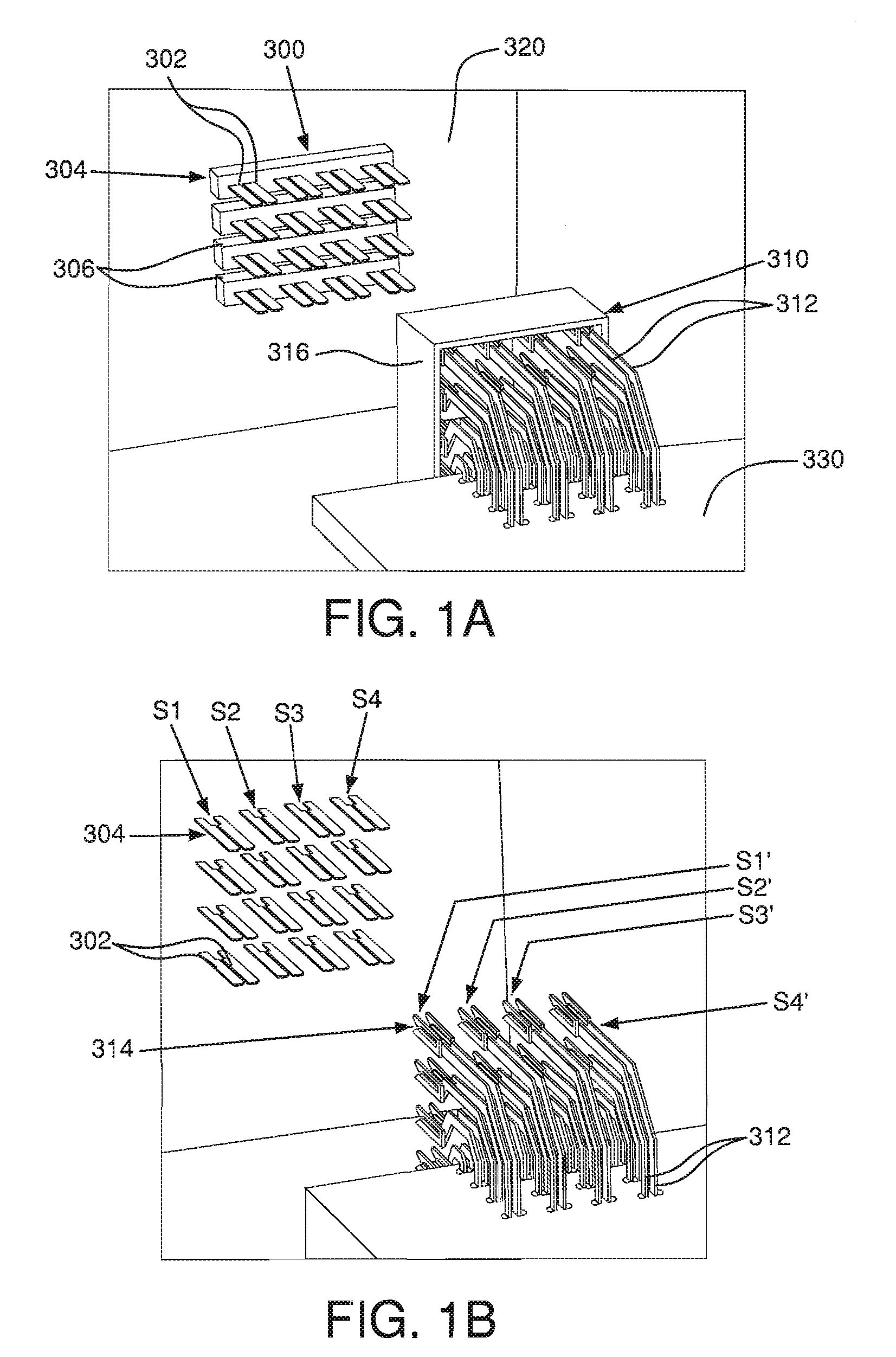
[0021]FIGS. 1A and 1B depict a connector system that includes a first connector 310 having an arrangement of broadside-coupled electrical contacts 312 and a second connector 300 having an arrangement of edge-coupled electrical contacts 302. The connector 300 may be a male, or plug, connector. The connector 310 may be a female, or receptacle, connector. The connector 300 may be a header connector, which may be mounted to a first circuit board 320, which may be a backplane. The connector 310 may be a right-angle connector, which may be mounted to a second circuit board 330, which may be a daughter card. The connector 310 may also be a mezzanine connector. The connectors 300, 310 may be mounted to their respective circuit boards 320, 330 via surface mount technology (SMT), solder ball grid array, press fit and the like.

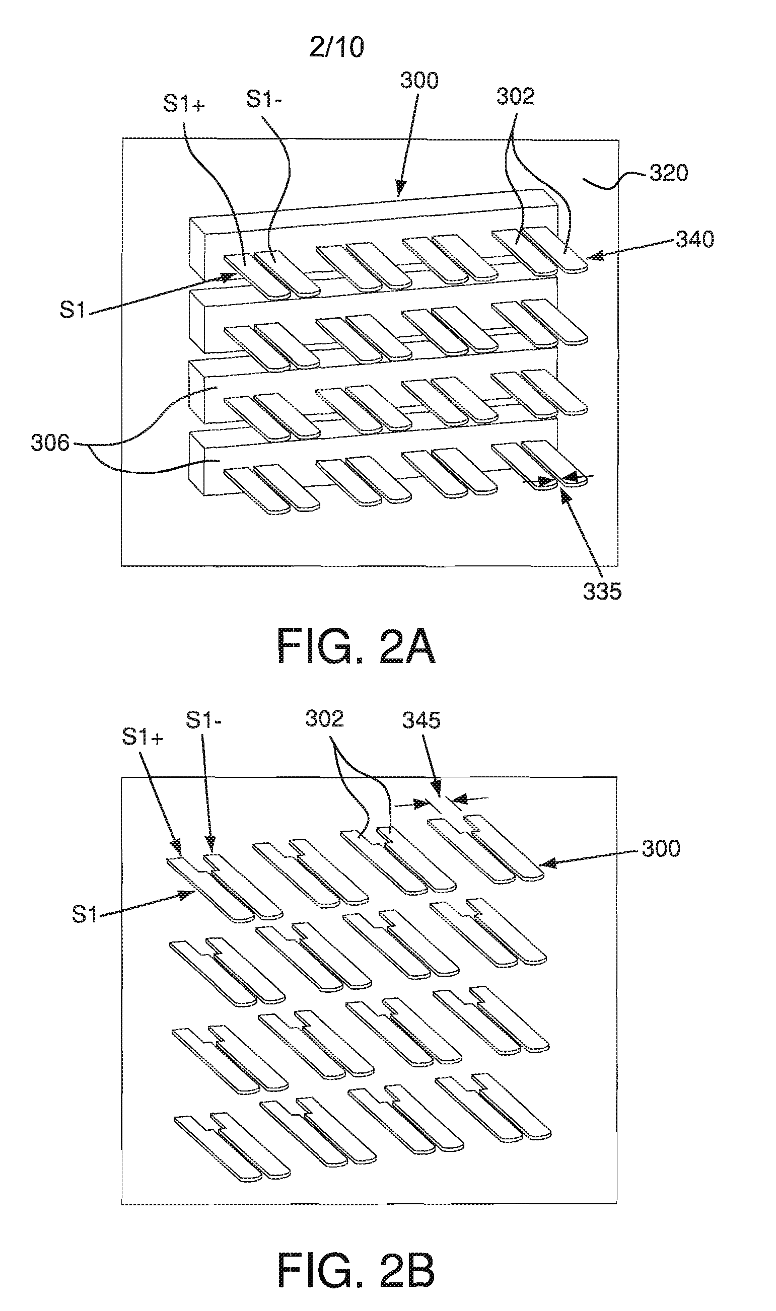
[0022]An edge-coupled pair of electrical contacts 302 may form a differential signal pair. As shown in FIG. 1B, a linear array 304 of edge-coupled electrical contacts 30...


PUM


Abstract

An electrical connector system is disclosed and may include a header connector and a receptacle connector. The contacts in the header connector may be edge-coupled to limit the level of cross-talk between adjacent signal contacts. For example, a differential signal in a first signal pair may produce a high-field in the gap between the contacts that form the signal pair, and a low-field near a second, adjacent signal pair. The contacts in the receptacle connector may be broadside-coupled and configured to receive the contacts from the header connector while minimizing signal skew. For example, the overall length of the contacts within a differential signal pair may be the same. The contacts in the connector system may include differential signal pairs, single-ended contacts, and / or ground contacts. The connector system may be devoid of any electrical shielding between the signal contacts.

Description

CROSS-REFERENCE TO RELATED APPLICATIONS[0001]The present application is related by subject matter to U.S. patent application Ser. No. 11 / 367,784, U.S. patent application Ser. No. 11 / 368,211, and U.S. patent application Ser. No. 11 / 367,745 the contents of each of which are hereby incorporated by reference in their entireties.FIELD OF THE INVENTION[0002]Generally, the invention relates to electrical connectors. More particularly, the invention relates to electrical connector systems having an interface for mating edge-coupled pairs of electrical contacts in a first connector with broadside-coupled pairs of electrical contacts in a second connector.BACKGROUND OF THE INVENTION[0003]Electrical connectors provide signal connections between electronic devices using signal contacts. Often, the signal contacts are so closely spaced that undesirable interference, or “cross-talk,” may occur between adjacent signal contacts. As used herein, the term “adjacent” refers to contacts (or rows or col...

Claims


Application Information

Patent Timeline
Patent Type & Authority Patents(United States)
IPC IPC(8): H01R13/648
CPCH01R12/724H01R13/6477H01R13/6461Y10S439/941
Inventor MINICH, STEVEN E.
Owner FCI AMERICAS TECH LLC
Why Eureka
Try Eureka