LED drive circuit, LED lighting device, and backlight
a driving circuit and led lighting technology, applied in pulse generators, pulse techniques, instruments, etc., can solve the problems of affecting product quality, uneven luminance, and different temperature rises and lifetimes, and achieve the effect of reducing the cost of production and maintenan
- Summary
- Abstract
- Description
- Claims
- Application Information
AI Technical Summary
Benefits of technology
Problems solved by technology
Method used
Image
Examples
embodiment 1
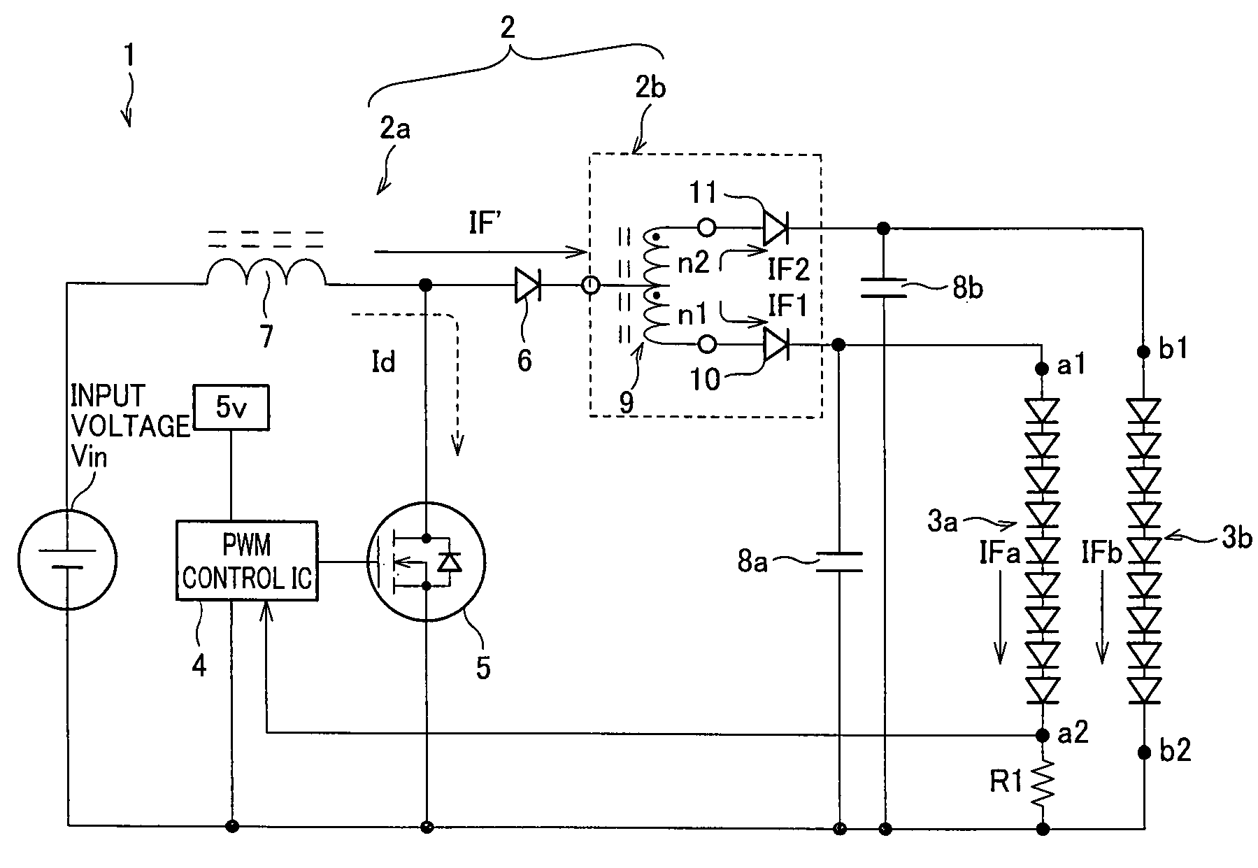
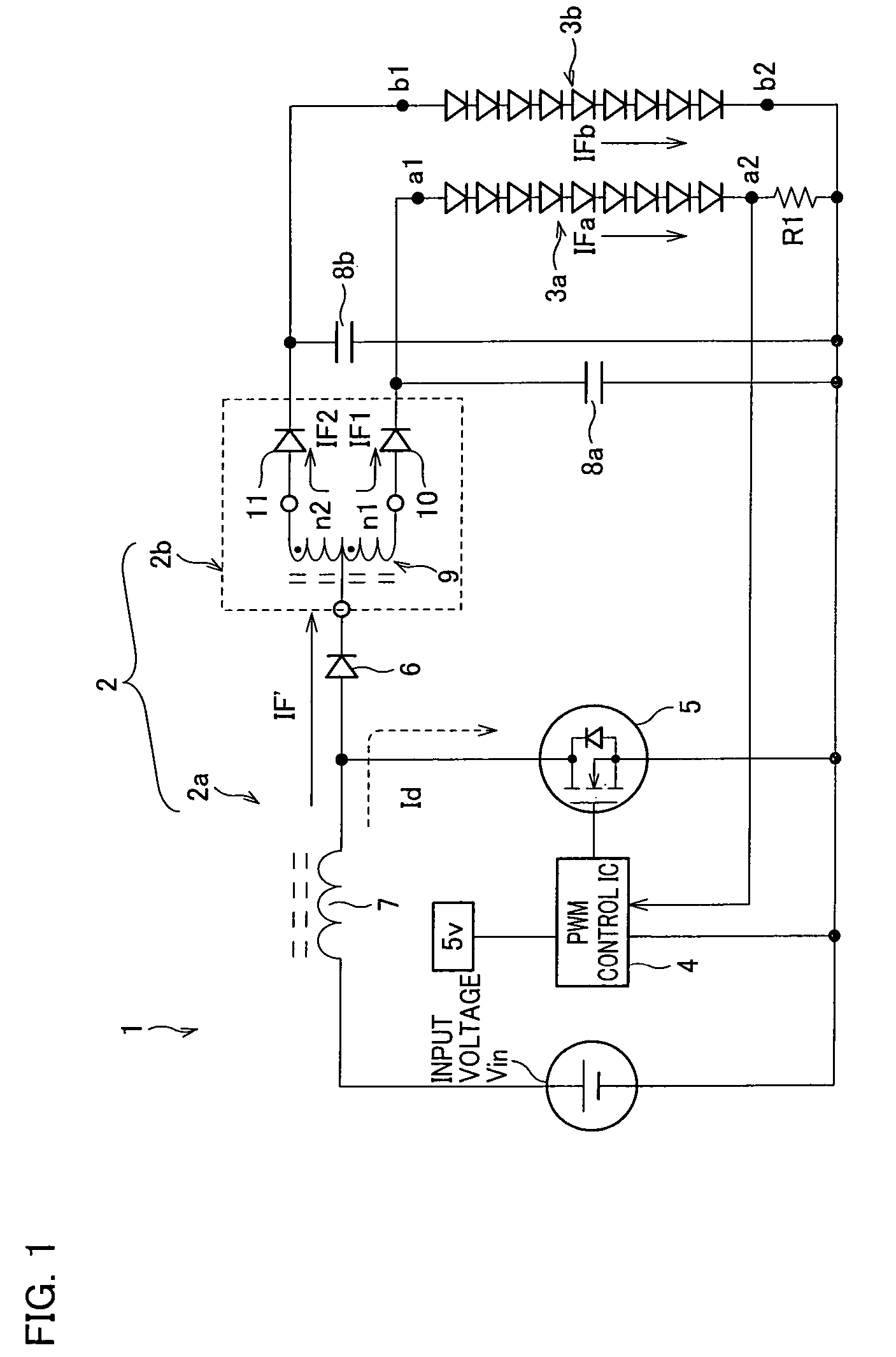
[0030]The following will describe an embodiment of the LED drive circuit of the present invention. FIG. 1 is a circuit diagram illustrating the arrangement of an LED lighting device for embodiment 1.
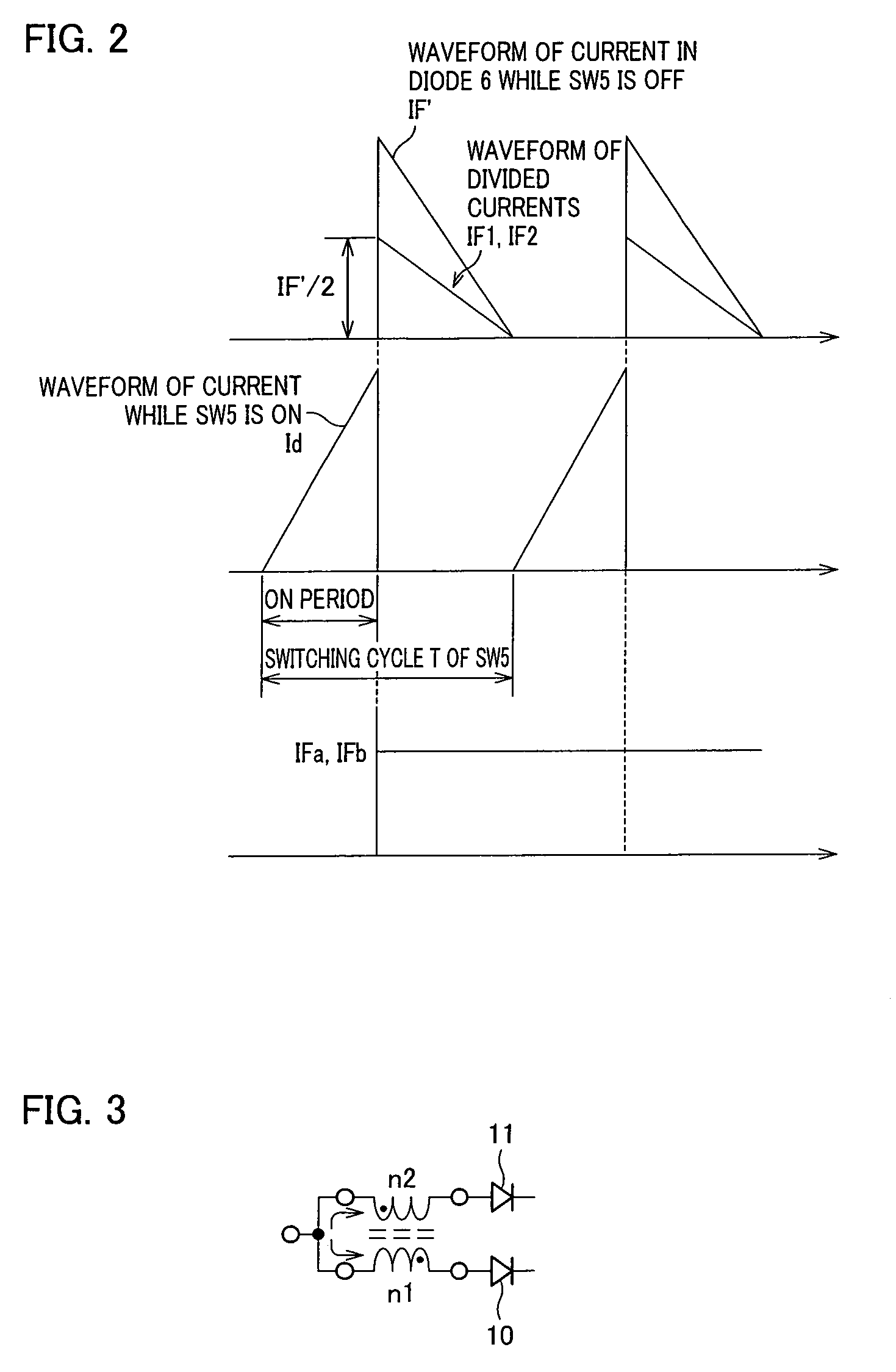
[0031]As shown in the figure, the LED lighting device 1 contains an input power supply Vin, an LED drive circuit 2, and two LED circuits 3a and 3b. The LED drive circuit 2 contains a switchable power supply circuit 2a and a current-dividing circuit 2b. The switchable power supply circuit 2a, connected to the input power supply Vin, contains a PWM control IC 4, a switching element 5 (N-channel MOS transistor), a diode 6, a coil 7, smoothing capacitors 8a and 8b, and a resistor R1. The current-dividing circuit 2b contains a current-dividing coil (inductor) 9 and diodes (reverse current blocking diodes) 10 and 11. The current-dividing coil 9 is made up of a winding n1 of n1 turns and a winding n2 of n2 turns, both wound around the same core, which are coupled together at a center tap (relay...
embodiment 2
[0041]The following will describe another embodiment of the LED drive circuit of the present invention. FIG. 4 is a circuit diagram illustrating the arrangement of an LED lighting device for embodiment 2.
[0042]As shown in the figure, the LED lighting device 101 contains an input power supply Vin, an LED drive circuit 102, and four LED circuits 103a to 103d. The LED drive circuit 102 contains a switchable power supply circuit 102a and a current-dividing circuit 102b. The switchable power supply circuit 102a, connected to the input power supply Vin, contains a PWM control IC 104, a switching element 105, a diode 106, a coil 107, smoothing capacitors 108a to 108d, and a resistor R2. The current-dividing circuit 102b contains current-dividing coils 109x to 109z and diodes 110 to 113 (reverse current blocking diodes). The current-dividing coils 109x to 109z are each made up of two windings wound around the same core which are coupled together at a center tap. The LED circuit 103a is made...
embodiment 3
[0049]The following will describe another embodiment of the LED drive circuit of the present invention. FIG. 6 is a circuit diagram illustrating the arrangement of an LED lighting device for embodiment 3.
[0050]As shown in the figure, the LED lighting device 201 contains an AC power supply, an LED drive circuit 202, and four LED circuits 203a to 203d. The LED drive circuit 202 contains a switchable power supply circuit 202a and a current-dividing circuit 202b. The switchable power supply circuit 202a, connected to the AC power supply, contains bridged diodes 220, a capacitor 221, resistors Ra and Rb, a PWM control IC 204, a switching element 205 (N-channel MOS transistor), a coil 207 (with a core), smoothing capacitors 208a to 208d, a photocoupler 255 (for both emission and receipt of light), and resistors R3 and R4. The current-dividing circuit 202b contains current-dividing coils 209x to 209z and diodes 210 to 213 (reverse current blocking diodes). The current-dividing coils 209x t...
PUM
 Abstract
Description
Claims
Application Information
 - R&D
- Intellectual Property
- Life Sciences
- Materials
- Tech Scout
- Unparalleled Data Quality
- Higher Quality Content
- 60% Fewer Hallucinations
Browse by: Latest US Patents, China's latest patents, Technical Efficacy Thesaurus, Application Domain, Technology Topic, Popular Technical Reports.
© 2025 PatSnap. All rights reserved.Legal|Privacy policy|Modern Slavery Act Transparency Statement|Sitemap|About US| Contact US: help@patsnap.com


