Engine braking method for a supercharged internal combustion engine

a technology of internal combustion engine and braking method, which is applied in the direction of machines/engines, non-mechanical valves, electrical control, etc., can solve the problem of a relatively small crank angle in the angular range of all valves closed during the compression stroke, and achieves a reduced load, lower load, and higher mass flow throughput

Inactive Publication Date: 2008-08-12
DAIMLER AG
View PDF24 Cites 7 Cited by
  • Summary
  • Abstract
  • Description
  • Claims
  • Application Information

AI Technical Summary

Benefits of technology

[0008]As compared with the four-stroke method, the two-stroke method leads, during engine braking, to markedly lower loads on the components of the internal combustion engine, since, in the two-stroke method, the internal combustion engine has a higher mass flow throughput during engine braking, this being accompanied, at comparable engine braking powers, by lower turbine inlet pressures and turbine inlet temperatures in the exhaust tract. On account of the reduced load, higher engine braking power than during four-stroke engine braking are possible. By means of the proposed engine braking method by two-stroke operation, not only are the internal combustion engine components, which are in contact with the throughput gases subjected to lower stresses, but the wear of the wheel brakes is also reduced, since a higher braking power load can be assumed by the engine brake so that the wheel brakes are relieved.
[0009]The increased air quantity which can pass through the internal combustion engine during two-stroke braking operation also leads to neutralizing the problem of compressor surge at high specific braking powers. With comparable engine braking powers, in the compressor characteristic map the engine braking line of two-stroke braking is at a greater distance from the surge limit than the engine braking line of four-stroke braking. A further reduction in the risk of engine pumping can be achieved, despite a higher engine braking power, by closing the outlet valve before the inlet valve is opened.
[0010]In the two-stroke engine braking phase, for sucking the normally highly compressed combustion air provided by the supercharging assembly, the cylinder inlet valve is opened as soon as the piston enters the region of bottom dead center. After the bottom dead center position is passed, the inlet valve is closed again, the corresponding cylinder then being in the compression phase in which all the valves are normally closed. When the top dead center position is approached, the outlet valve is opened with the result that the compressed air is discharged into the exhaust tract in a very short time because of the high cylinder internal pressure. After the top dead center position has been overshot, that is to say during the expansion stroke, the outlet valve is closed again. A complete work cycle is thereby concluded.
[0014]According to a first advantageous version, the outlet closing time point of the outlet valve lies even before the inlet opening time point of the inlet valve, so that, for a short time span before the opening of the inlet valve, all the charge exchange valves are closed, and an overflow of gas, in particular out of the exhaust tract via the cylinder inner space back into the intake tract is prevented.

Problems solved by technology

However, because of the late inlet closing time point and the already shortly following outlet opening time, the angular range in which all the valves are closed during the compression stroke is restricted to a relatively small crank angle range.

Method used


Image

  • Engine braking method for a supercharged internal combustion engine
  • Engine braking method for a supercharged internal combustion engine
  • Engine braking method for a supercharged internal combustion engine

Examples


Embodiment Construction

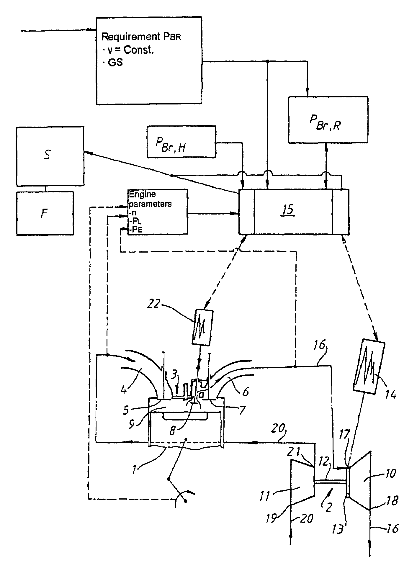
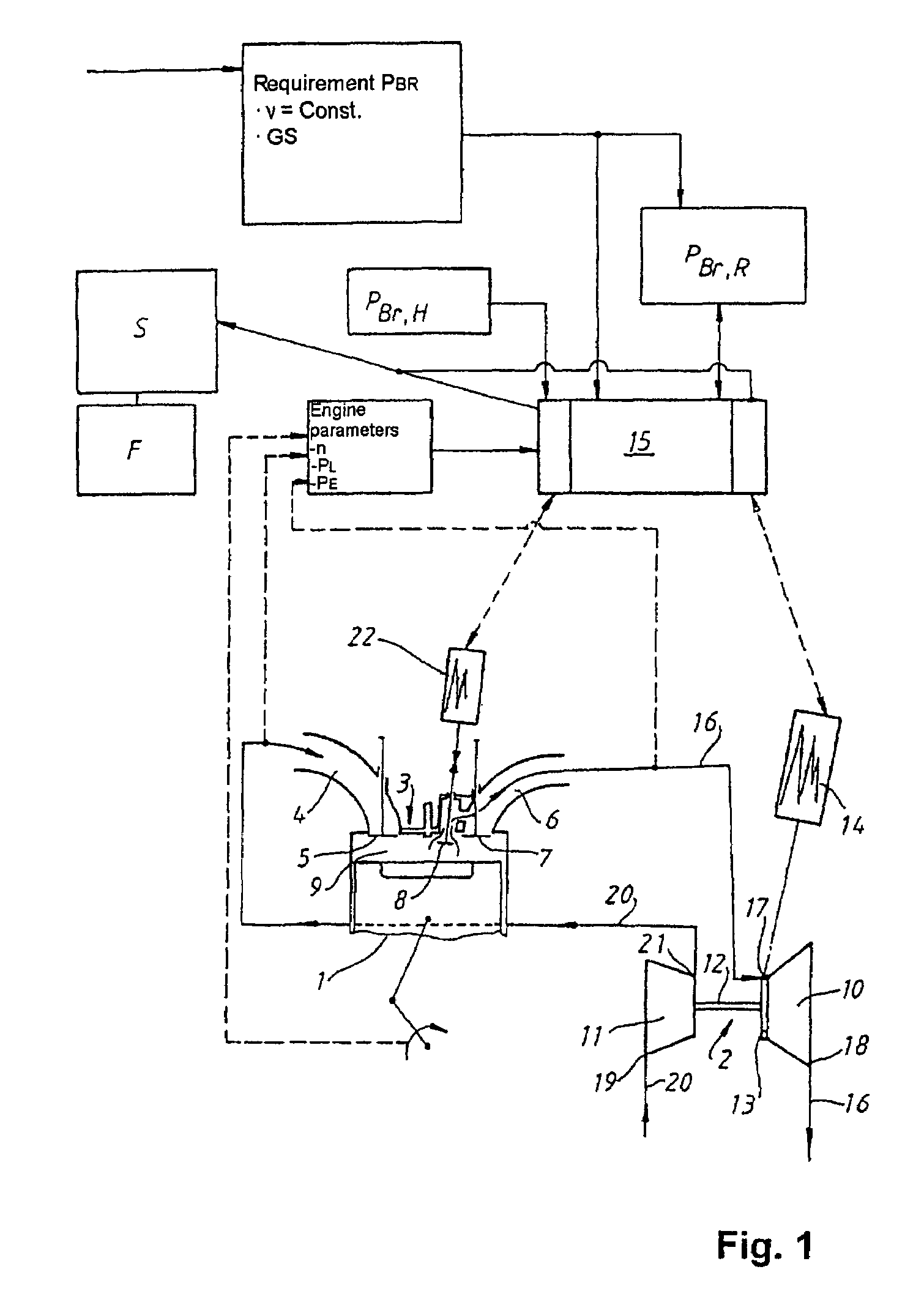
[0024]In the internal combustion engine shown in a diagrammatic illustration in FIG. 1, a cylinder 1 with charge exchange valves 5, 7 in the cylinder head 3 is illustrated. The internal combustion engine includes an exhaust gas turbocharger 2 which comprises an exhaust gas turbine 10 in the exhaust line 16 of the internal combustion engine and a compressor 11 in the intake tract 20, the turbine wheel being rotationally coupled to the compressor wheel via a shaft 12. The exhaust gas turbine 10 is equipped with a variable turbine geometry 13 for variably setting the effective turbine inlet cross section, the variable turbine geometry being adjustable via an actuator 14.

[0025]The combustion air is first supplied, in the intake tract 20, via the compressor inlet 19 to the compressor wheel in the compressor 11, is compressed there and enters the cylinder inlet via the compressor outlet 21. With the inlet valve 5 open, the compressed combustion air is supplied via an inlet duct 4 of the i...


PUM


Abstract

In an engine braking method for a supercharged internal combustion engine, wherein combustion air, which is under boost pressure and is supplied to the cylinders under the control of engine inlet and outlet valves, is compressed in the cylinders and is subsequently discharged into the exhaust tract, engine braking takes place in a two-stroke operating mode.

Description

[0001]This is a Continuation-In-Part Application of International application PCT / EP2005 / 05227 filed May 13, 2005.BACKGROUND OF THE INVENTION[0002]The invention relates to an engine braking method for a supercharged internal combustion engine.[0003]An engine braking method is known from DE 196 37 999 A1. The internal combustion engine is equipped with an exhaust gas turbocharger, the exhaust gas turbine of which is provided with a variable turbine geometry for variably setting the effective turbine inlet flow cross section. To achieve high engine braking power, the variable turbine geometry is adjusted into a blocking position reducing the cross section, with the result that the exhaust back pressure between the cylinder outlets and the exhaust gas turbine rises. The engine braking power is regulated via a controller in the internal combustion engine as a function of current engine and operating variables and also of the driver's instruction by a variation in the opening curve of a ...

Claims


Application Information

Patent Timeline
Patent Type & Authority Patents(United States)
IPC IPC(8): F02D13/04F02B33/00
CPCF01L1/38F01L13/06F01L13/065F02D13/04F02D41/0005F02D41/0007F01L9/02F01L9/04F01L2800/00Y02T10/42F02B37/24F02D2041/001Y02T10/144F02B37/00Y02T10/12Y02T10/40F01L9/10F01L9/20
Inventor BENZ, MICHAELKRATSCHMER, STEPHANSCHMIDT, ERWINSTADELMAIER, ALEXANDERSUMSER, SIEGFRIED
Owner DAIMLER AG
Why Eureka
Try Eureka