Security monitoring methodology using digital audio

a technology of security monitoring and digital audio, applied in the direction of digital computer details, frequency-division multiplex, instruments, etc., can solve the problems of inability of monitoring system inability to supervise the availability of field panels, and inability to achieve the supervision of communications at low cost, so as to improve the quality of service and speed up connection time

Active Publication Date: 2008-08-12
ADVANTOR SYST +1
View PDF1 Cites 5 Cited by
  • Summary
  • Abstract
  • Description
  • Claims
  • Application Information

AI Technical Summary

Benefits of technology

[0009]The use of digital networks for communications provides much faster connection time (typically less than one second) and the ability to supervise communications at low cost.
[0010]An object of the present invention is to improve the quality of service in the fidelity of audio monitoring and recording.
[0012]A further object of the present invention is to provide a cost-effective means for supervising field equipment and provide much greater efficiencies of scale within the central monitoring center environment, in that individual channels of audio may be routed according to workstation availability.

Problems solved by technology

However, in this method, the receiver equipment does not provide the ability to route the audio signals among available workstations, creating limitations to scale and workstation efficiency.
In addition, with dial-up applications, there is no ability for the monitoring system to supervise the availability of the field panels, and the length of time to establish communications can take on the order of 10 seconds or more.
The only alternative, using analog telephony is costly dedicated telephone lines.
Further, in applications requiring the delivery of security data and assessment audio from a physical security panel to a monitoring center over a secure digital network, no commercial solution currently exists because of the extensive design and development required for the system-level components, of which the subject device is one, and infrastructure support software, drivers and middleware for the monitoring environment.

Method used


Image

  • Security monitoring methodology using digital audio
  • Security monitoring methodology using digital audio
  • Security monitoring methodology using digital audio

Examples


Embodiment Construction

[0022]In the following description, it is to be understood that the use of relational terms, if any, such as first and second, top and bottom, left and right, and the like are used to distinguish one from another entity or action without necessarily, by themselves, requiring or implying any actual such relationship or order between such entities or actions.

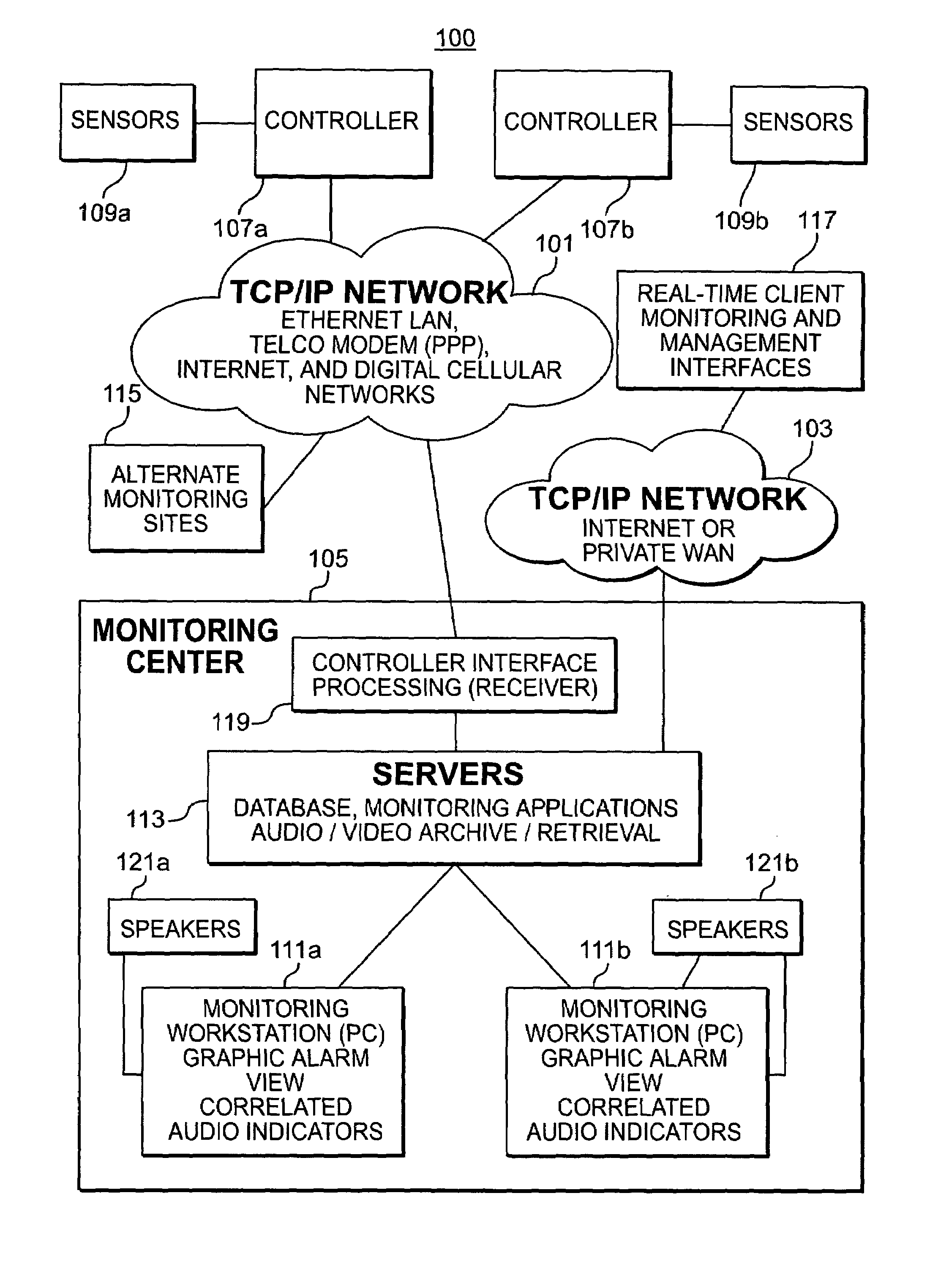
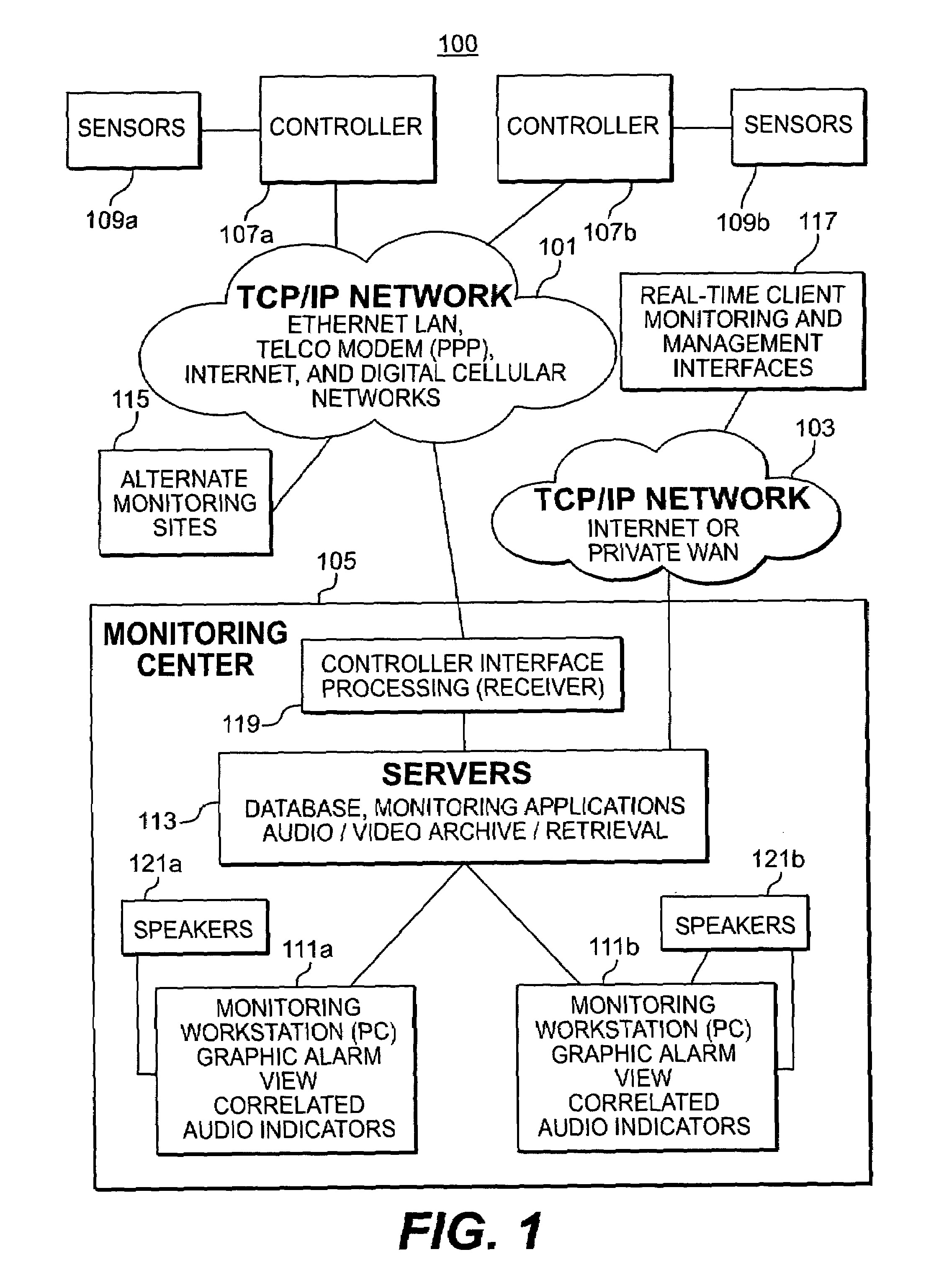
[0023]As shown in FIG. 1, an overview of a security monitoring system 100 includes a TCP / IP Network 101 and 103 in the top half of the drawing and a monitoring center 105 in the bottom half of the drawing.

[0024]The present invention overcomes the limitations of the prior art by using high-speed network connections to the monitoring center 105. The TCP / IP Network 101 may be an Ethernet LAN, Telco Modem (PPP), Internet, or digital cellular network. The TCP / IP Network 103 may be the public Internet or a private LAN or WAN network. A cable-modem, DSL, or wireless connection can also be used.

[0025]A controller 107a and 107b connects to...


PUM


Abstract

A security monitoring methodology and device using digital audio. A security control device integrates physical intrusion detection functions, physical access control functions, and compressed, streaming, digital audio transmission capability. The device provides interfaces for a number of sensor inputs, including standard alarm monitoring sensors and audio sensors. The device is capable of communicating with a monitoring system over a variety of digital networking configurations options, including TCP / IP, via embedded Ethernet interface, or serial modem communications over telephone or digital cellular networks using PPP network protocol. The device may use backup channels of communications including telephone and cellular network communications. All communications with the device, whether to monitoring receiver or other local devices, may be secured with a minimum AES 128-bit encryption.

Description

BACKGROUND OF THE INVENTION[0001]1. Field of the Invention[0002]The present invention relates generally to physical security monitoring and physical access control where bi-directional communications is provided via a digital network and audio signals are used in the assessment of physical security alarm events.[0003]2. Description of Related Art[0004]Many conventional alarm monitoring systems provide the ability to configure listen-in assessment or “two-way voice” features by connecting panel equipment connected to an alarm premises to a telephone handset of an operator within a monitoring center. This conventional method uses analog telephony and the audio channel “piggy-backs” on the alarm transmission. One company that uses this method in a high-volume commercial central monitoring center is Computerized Monitoring Services (CMS) in Longwood, Fla.[0005]Sonitrol Corporation in Berwyn, Pa. offers a sophisticated approach to monitoring simultaneous analog audio signals by a single ...

Claims


Application Information

Patent Timeline
Patent Type & Authority Patents(United States)
IPC IPC(8): G08B1/00G08B25/14
CPCG08B25/14
Inventor PERKINSON, CHARLESLUSAKA, PATRICK
Owner ADVANTOR SYST
Why Eureka
Try Eureka