Disk drive servo control using spirals

a technology of servo control and disk drive, applied in the direction of maintaining head carrier alignment, digital recording, instruments, etc., can solve the problems of spirals, however, being sometimes written imperfectly, and traditional servo writing methods, however, become impractical, and achieve the effect of minimizing phase errors

Inactive Publication Date: 2008-08-12
MARVELL ASIA PTE LTD
View PDF4 Cites 41 Cited by
  • Summary
  • Abstract
  • Description
  • Claims
  • Application Information

AI Technical Summary

Benefits of technology

[0036]In another feature, the computer program further comprises detecting a phase error between time stamps of a plurality of reference servo marks and minimizing the phase error. The computer program further comprises selecting a first time stamp that differs from a second time stamp by a time that is substantially equal to a predetermined time. The computer program further comprises calculating a raw timing error by comparing the first time stamp with an expected time stamp. The computer program further comprises calculating a modulus of the raw timing error and generating a phase error signal. The computer program further comprises using the phase error signal to synchronize a self-servo write (SSW) clock to a reference servo sector (RSS) clock derived from the spiral signals.

Problems solved by technology

The traditional servo writing methods, however, become impractical as the track density increases for a disk drive.
The increasing track density also makes traditional servo writing physically impractical.
The spirals, however, are sometimes written imperfectly.
Additionally, the actuator arm may not be perfectly steady when positioned onto an RSS.
Consequently, a head may not be able to quickly and accurately lock onto an RSS as the head moves across a platter.

Method used


Image

  • Disk drive servo control using spirals
  • Disk drive servo control using spirals
  • Disk drive servo control using spirals

Examples


Embodiment Construction

[0067]The following description of the preferred embodiment(s) is merely exemplary in nature and is in no way intended to limit the invention, its application, or uses. For purposes of clarity, the same reference numbers will be used in the drawings to identify similar elements. As used herein, the term module, circuit and / or device refers to an Application Specific Integrated Circuit (ASIC), an electronic circuit, a processor (shared, dedicated, or group) and memory that execute one or more software or firmware programs, a combinational logic circuit, and / or other suitable components that provide the described functionality. As used herein, the phrase at least one of A, B, and C should be construed to mean a logical (A or B or C), using a non-exclusive logical or. It should be understood that steps within a method may be executed in different order without altering the principles of the present invention.

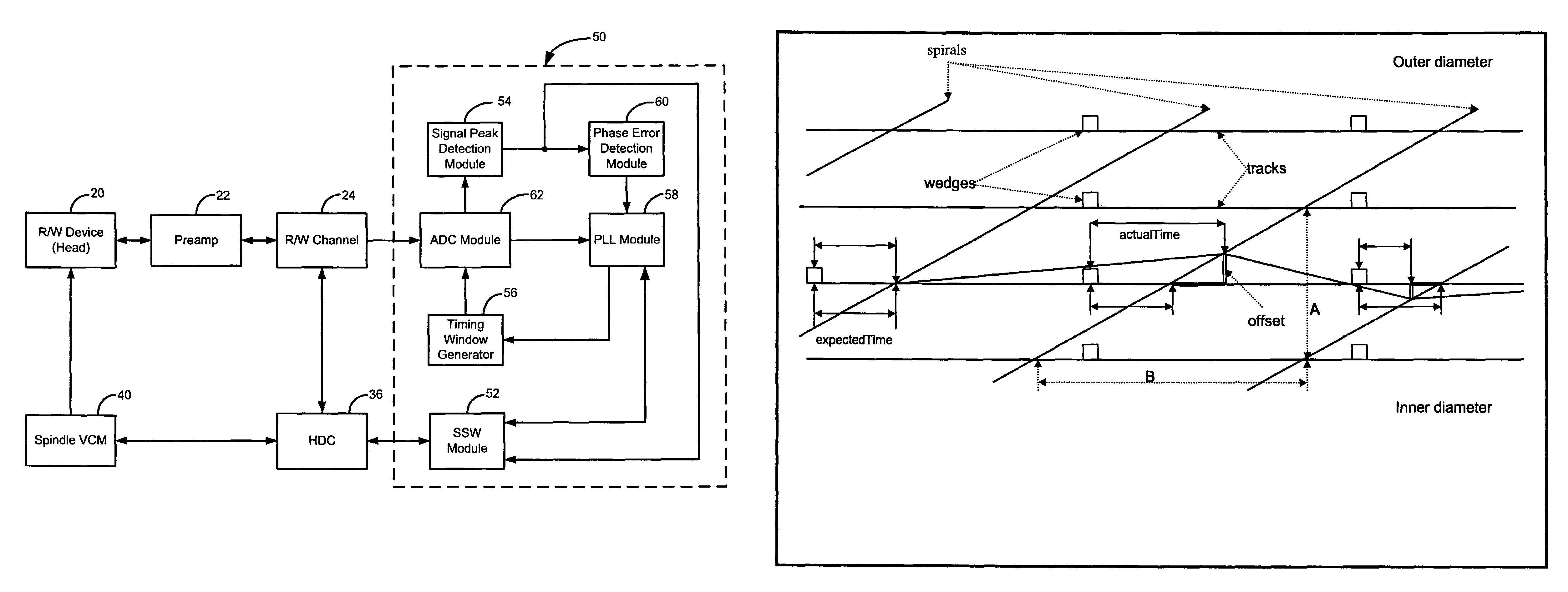
[0068]Referring now to FIG. 3, a system 50 for disk drive servo control using ...


PUM

PropertyMeasurementUnit
radial distanceaaaaaaaaaa
actual timeaaaaaaaaaa
timeaaaaaaaaaa

Abstract

A servo control system includes a peak detection module that detects peak times of spiral signals generated by reading spirals prewritten on a magnetic medium. The servo control system includes a control module that determines positions of the spirals based on the peak times, stores the positions of the spirals, seeks and tracks the spirals using the positions, and writes servo on the magnetic medium based on the positions of the spirals.

Description

FIELD OF THE INVENTION[0001]The present invention relates to computer disk drives, and more particularly to disk drive servo control systems using spirals.BACKGROUND OF THE INVENTION[0002]Host devices such as computers, laptops, personal video recorders (PVRs), MP3 players, game consoles, servers, set-top boxes, digital cameras, and / or other electronic devices often need to store a large amount of data. Storage devices such as hard disk drives (HDD) may be used to meet these storage requirements.[0003]Referring now to FIG. 1, an exemplary hard disk drive (HDD) 10 is shown to include a hard disk drive (HDD) system 12 and a hard drive assembly (HDA) 13. The HDA 13 includes a magnetic medium or one or more platters 14. The platters 14 are coated with magnetic layers 15. The magnetic layers 15 store positive and negative magnetic fields that represent binary 1's and 0's. A spindle motor, shown schematically at 16, rotates the hard drive platters 14. Generally, the spindle motor 16 rotat...

Claims


Application Information

Patent Timeline
Patent Type & Authority Patents(United States)
IPC IPC(8): G11B21/02
CPCG11B5/59661G11B5/59688G11B5/59666
Inventor CHEUNG, MANNEOS, PERRY
Owner MARVELL ASIA PTE LTD
Why Eureka
Try Eureka