Method for determining fill level on the basis of travel time of a high-frequency measuring signal

a high-frequency measuring signal and fill level technology, applied in the direction of liquid/fluent solid measurement, volume measurement apparatus/methods, reradiation, etc., can solve the problems of complex production, high cost of purchase, no suitable, cost-effective data-processing units, etc., to achieve more precise and stable results

Active Publication Date: 2008-08-12
EHNDRESS KHAUZER GMBKH KO KG
View PDF4 Cites 26 Cited by
  • Summary
  • Abstract
  • Description
  • Claims
  • Application Information

AI Technical Summary

Benefits of technology

[0023]Furthermore, it is provided that, at a third tolerance value of a small or tendential control deviation of the difference frequency from the desired value of the difference frequency, or of the difference time from the desired value of the difference time, it is not immediately counter-controlled with an appropriate control variable; rather, a tendency of the control deviations is determined, and a tendential control signal is produced, which is joined to the subsequent pulse-sequence-modulated control signals, or on the pulse-width-modulated control signals. If the present control deviation of the difference time lies, for example, in the range of a few μs (microseconds), and / or this corresponds to a tendential control deviation, then it is not immediately corrected; rather, these most minimal changes are taken into consideration in the later pulse-sequence-modulated or pulse-width-modulated control signals. Since such small control deviations below the third tolerance value can be only very difficultly corrected by a subsequent readjusting or updating of the control variable, the mathematical integration of these tendential control deviations into the large and medium control deviations affords a possibility to construct the control such that it is more precise and more stable. As a result, an overshooting and a subsequent settling of the control can be avoided.

Problems solved by technology

A general problem in the case of all travel time measuring methods using high-frequency measuring signals in the GHz (Gigahertz) region is that, for the evaluation of high-frequency measuring signals, high-frequency components, which are designed for such high-frequency ranges, must be used.
These high-frequency components have the disadvantage that they are complex to produce and very expensive to purchase.
This additional processing step is carried out because there are no suitable, cost-effective data-processing units, e.g. DSPs (Digital Signal Processors) which can reliably process high-frequency measuring signals.
This phase shift corresponds to a linearly-increasing time delay.
A disadvantage of regulating the difference frequency to a desired value according the state of the art is that such a control takes a very long time, and, under certain conditions, results in regulating to an incorrect desired value of the difference frequency.

Method used


Image

  • Method for determining fill level on the basis of travel time of a high-frequency measuring signal
  • Method for determining fill level on the basis of travel time of a high-frequency measuring signal
  • Method for determining fill level on the basis of travel time of a high-frequency measuring signal

Examples


Embodiment Construction

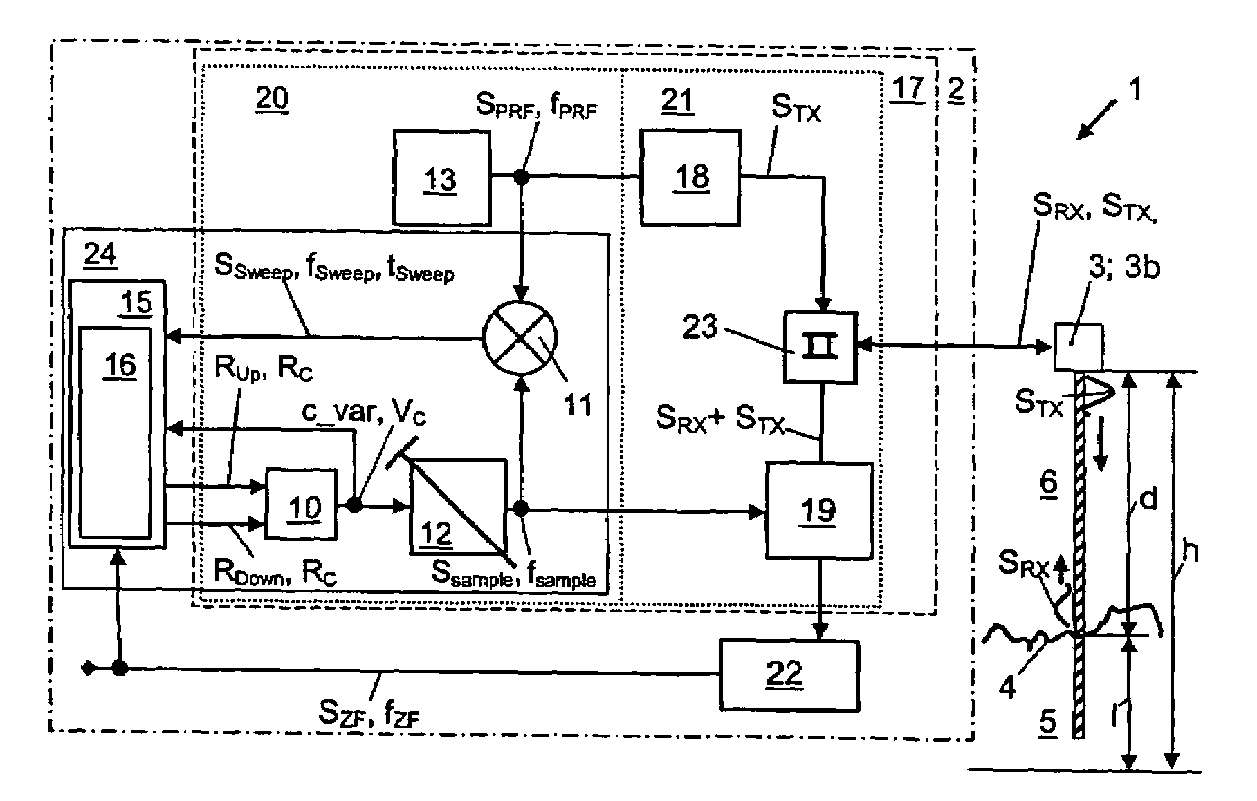
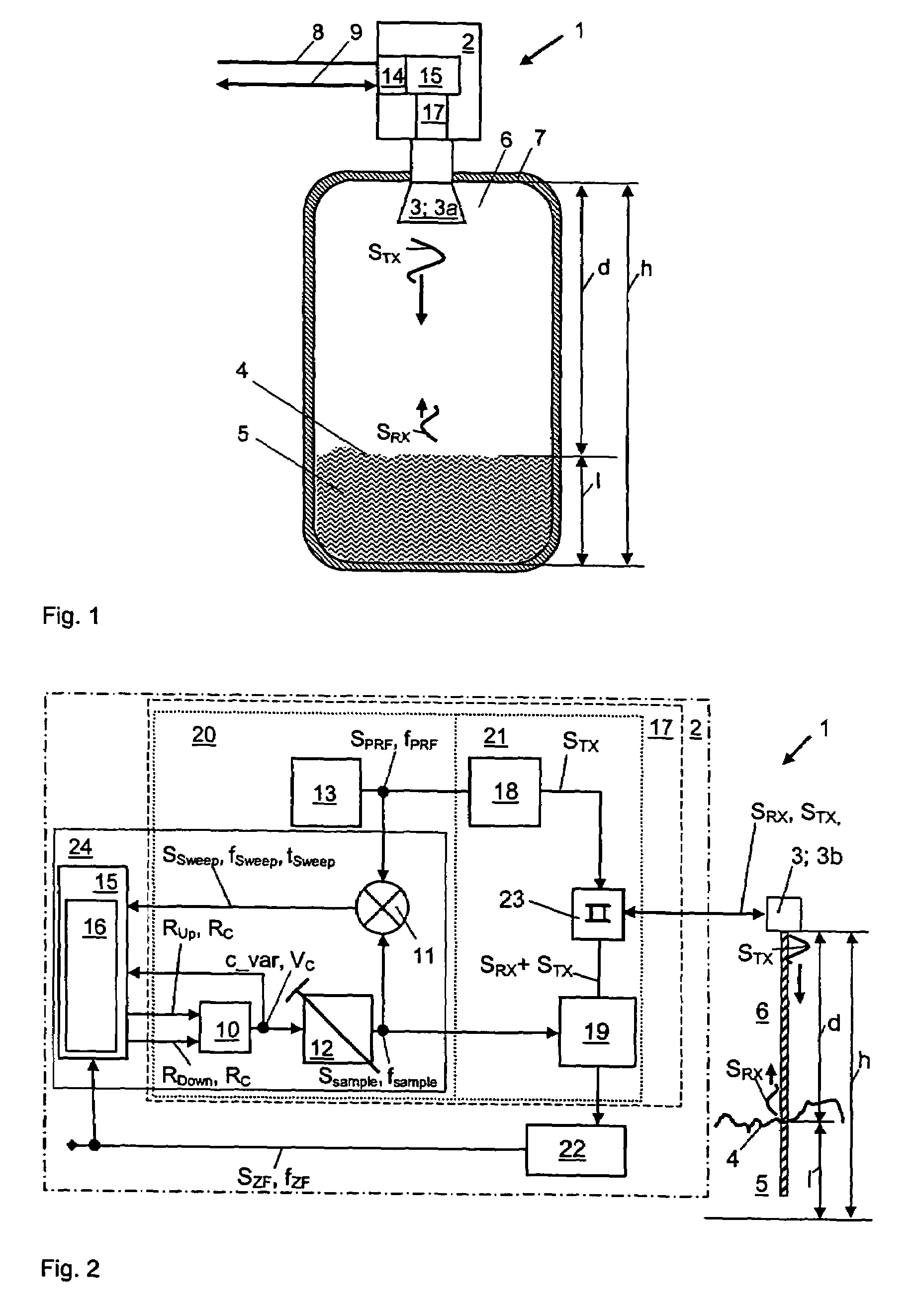
[0029]FIG. 1 shows an example of an embodiment of the apparatus 1 of the invention for determining the distance d, or the fill level l, on the basis of the travel time t of high-frequency measuring signals SHF. For this purpose, apparatus 1 includes primarily a measuring unit 3 connected with the measuring transmitter 2, by means of which the high-frequency measuring signal SHF, or the transmission signal STX, is coupled, and emitted, into a process space 6 in the container 7 bounding the fill substance 5. The measuring unit 3 is directed into the process space 6 of the container 7 through an opening, e.g. a nozzle. The measuring unit 3, or the transducer element, as shown in FIG. 1, can be configured as an antenna 3a, and especially as a horn antenna, a rod antenna, a parabolic antenna, or also a planar antenna, which freely radiates the transmission signal STX, into the process space 6 of the container 7. Instead of the antenna 3a freely radiating into the process space 6, a surfa...


PUM


Abstract

A method for determining the fill level (l) on the basis of the travel time (t) of a high-frequency measuring signal (SHF), which is transformed into a lower frequency, intermediate-frequency measuring signal (SZF), wherein the transformation factor (KT) is obtained from a difference frequency (fSweep) between a pulse repetition frequency (fPRF) and a sampling frequency (fsample) The pulse repetition frequency (fPRF) or the sampling frequency (fsample) is altered on the basis of a control with a control variable (c_var) through an appropriate control algorithm, such that a desired value (fSweep<sub2>—</sub2>setpoint) of the difference frequency is controlled to; wherein a gradient (grad) of at least two values is determined, and on the basis of the gradient (grad) and the difference frequency (fSweep), or difference time (tSweep), in the case of a set control variable (c_var), an operating point (OP) of the control is determined, and the control algorithm is adjusted accordingly thereto.

Description

FIELD OF THE INVENTION[0001]The present invention relates to a method for determining fill level based on the travel time of a high-frequency measuring signal, which, by means of a transformation method having a certain transformation factor, is transformed into a lower frequency, intermediate-frequency signal.BACKGROUND OF THE INVENTION[0002]Such methods for determining and monitoring fill level in a container are often used in measuring devices in the fields of automation- and process control technology. For example, measuring devices under the names Micropilot or Levelflex are produced and sold by the assignee. These measuring devices function according to the travel-time measurement method, and serve for determining and / or monitoring a fill level of a medium in a container. In the guided microwave method, or the TDR (Time Domain Reflection) method, a high-frequency pulse is emitted along a Sommerfeld or Goubau wave guide, or along a coaxial wave guide. This pulse, upon meeting a...

Claims


Application Information

Patent Timeline
Patent Type & Authority Patents(United States)
IPC IPC(8): G01F17/00G01F23/00G06F19/00
CPCG01F23/284G01S13/88G01S13/10G01S7/285
Inventor MICHALSKI, BERNHARDBUSER, DOMINIKSCHERR, STEFAN
Owner EHNDRESS KHAUZER GMBKH KO KG
Why Eureka
Try Eureka