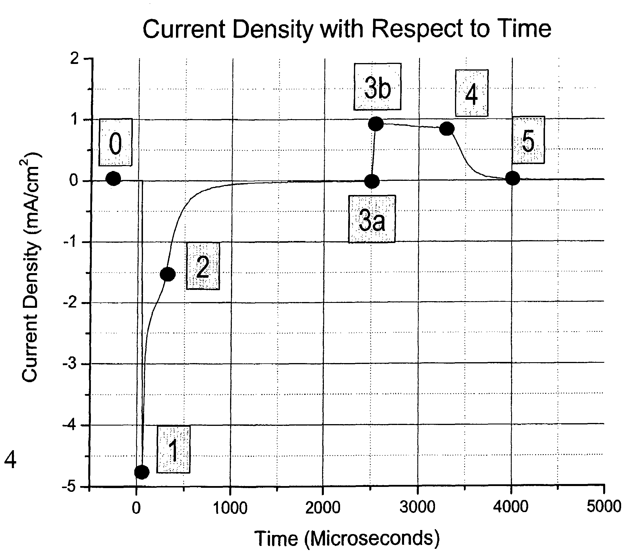
[0012]The invention relates, in an embodiment, to a method for controlling a substrate processing process, the substrate processing process being configured to process a substrate using plasma in a substrate processing chamber. The method includes providing a PIF (planar ion flux) measurement arrangement, the PIF measurement arrangement including at least a PIF probe that has a surface exposed to a plasma sheath of the plasma while the substrate is processed by the plasma. The method also includes alternately creating a charging phase and a quiescent phase for the PIF arrangement using an energy source that is configured to provide energy to the plasma via the PIF probe. The method additionally includes ascertaining a time tpoint2, the time tpoint2 representing a time during the charging phase of the PIF measurement arrangement wherein a first potential difference across the plasma sheath equals the plasma potential of the plasma. The method further includes ascertaining a time tpoint3a, the time tpoint3a representing a time during the charging phase of the PIF measurement arrangement wherein a second potential difference across the plasma sheath equals a floating potential, the floating potential representing a value of a potential difference across the plasma sheath during the charging phase when no current flows through the PIF probe. The floating potential at time tpoint3 is achieved while RF is applied to the PIF probe. Furthermore, the method includes generating a control signal to create at least one of an alarm and a transition in the substrate processing process if a time difference between the time tpoint2 and the time tpoint3a meets a predefined condition.
[0013]In another embodiment, the invention relates to a method for controlling a substrate processing process, the substrate processing process being configured to process a substrate using plasma in a substrate processing chamber. The method includes providing a PIF (planar ion flux) measurement arrangement, the PIF measurement arrangement including at least a PIF probe that has a surface exposed to a plasma sheath of the plasma while the substrate is processed by the plasma. The method also includes alternately creating a charging phase and a quiescent phase for the PIF arrangement using an energy source that is configured to provide energy to the plasma via the PIF probe. The method additionally includes ascertaining a time tpoint2, the time tpoint2 representing a time during the charging phase of the PIF measurement arrangement wherein a first potential difference across the plasma sheath equals to the plasma potential of the plasma. The method further includes ascertaining a probe bias voltage at the time tpoint2, the probe bias voltage at the time tpoint2 representing a potential difference between the surface of the PIF probe and ground at the at the time tpoint2. The method also includes generating a control signal to create at least one of an alarm and a transition in the substrate processing process if the probe bias voltage at the time tpoint2 meets a predefined condition.
[0014]In yet another embodiment, the invention relates to a method for controlling a substrate processing process, the substrate processing process being configured to process a substrate using plasma in a substrate processing chamber. The method includes providing a PIF (planar ion flux) measurement arrangement, the PIF measurement arrangement including at least a PIF probe that has a surface exposed to a plasma sheath of the plasma while the substrate is processed by the plasma. The method additionally includes alternately creating a charging phase and a quiescent phase for the PIF arrangement using an energy source that is configured to provide energy to the plasma via the PIF probe. The method further includes ascertaining a time tpoint2, the time tpoint2 representing a time during the charging phase of the PIF measurement arrangement wherein a first potential difference across the plasma sheath equals to a plasma potential of the plasma. The method also includes ascertaining a probe bias voltage at the time tpoint2, the probe bias voltage at the time tpoint2 representing a second potential difference between the surface of the PIF probe and ground at the at the time tpoint2. The method also includes ascertaining a time tpoint3a, the time tpoint3a representing a time during the charging phase of the PIF measurement arrangement wherein a second potential difference across the plasma sheath equals a floating potential in the presence of an applied RF signal to the probe, the floating potential representing a value of a third potential difference across the plasma sheath during the charging phase when no current flows through the PIF probe. The method further includes ascertaining a probe bias voltage at the time tpoint3b, the probe bias voltage at the time tpoint3b representing a fourth potential difference between the surface of the PIF probe and the ground at the at the time tpoint3b. This fourth point represents conditions at the moment of removal of the applied RF to the probe surface. The method also includes ascertaining a difference between the probe bias voltage at the time tpoint2 and the probe bias voltage at the time tpoint3b. Still further, the method includes generating a control signal to create at least one of an alarm and a transition in the substrate processing process if the difference between the difference between the probe bias voltage at the time tpoint2 and the probe bias voltage at the time tpoint3b meets a predefined condition.
[0015]In another embodiment, the invention relates to a method for controlling a substrate processing process, the substrate processing process being configured to process a substrate using plasma in a substrate processing chamber. The method includes providing a PIF (planar ion flux) measurement arrangement, the PIF measurement arrangement including at least a PIF probe that has a surface exposed to a plasma sheath of the plasma while the substrate is processed by the plasma. The method further includes alternately creating a charging phase and a quiescent phase for the PIF arrangement using an energy source that is configured to provide energy to the plasma via the PIF probe. The method additionally includes ascertaining a time tpoint2, the time tpoint2 representing a time during the charging phase of the PIF measurement arrangement wherein a first potential difference across the plasma sheath equals to a plasma potential of the plasma. The method also includes ascertaining a probe bias voltage at the time tpoint2, the probe bias voltage at the time tpoint2 representing a second potential difference between the surface of the PIF probe and ground at the at the time tpoint2. Still further, the method includes ascertaining a time tpoint3a, the time tpoint3a representing a time during the charging phase of the PIF measurement arrangement wherein a second potential difference across the plasma sheath equals a floating potential, the floating potential representing a value of a third potential difference across the plasma sheath during the charging phase when no current flows through the PIF probe. The method also includes ascertaining a probe bias voltage at the time tpoint3b, the probe bias voltage at the time tpoint3b representing a fourth potential difference between the surface of the PIF probe and the ground at the at the time tpoint3b. The method further includes ascertaining a difference between the probe bias voltage at the time tpoint2 and the probe bias voltage at the time tpoint3b. The method includes ascertaining an electron temperature of the plasma using the difference between the probe bias voltage at the time tpoint2 and the probe bias voltage at the time tpoint3 and a effective ion mass value. The method further includes generating a control signal to create at least one of an alarm and a transition in the substrate processing process if the electron temperature meets a predefined condition.

