Engine torque control device

a torque control and engine technology, applied in the direction of electric control, gearing control, gearing elements, etc., can solve the problems of reducing engine speed, shifting takes even longer to complete, and correspondingly longer shift time, so as to shorten the shift time, reduce the shock of shifting, and improve the effect of shifting

Active Publication Date: 2008-08-26
NISSAN MOTOR CO LTD
View PDF11 Cites 9 Cited by
  • Summary
  • Abstract
  • Description
  • Claims
  • Application Information

AI Technical Summary

Benefits of technology

[0009]The present invention was conceived in light of these problems encountered in the past. One object of the present invention is to afford better shifting by lessening shift shock while shortening the shift time by quickly commencing control (synchronizing control) whereby during a shift, engine speed is brought closer to the post-shift speed.

Problems solved by technology

It has been discovered that when, as discussed above, engine output is increased after a higher gear clutch has begun to slip, this slippage decreases engine speed and the shift takes correspondingly longer to complete, and when the torque converter is not locked up, the decrease in engine speed caused by the torque converter has to be made up, which means that the shift takes even longer to complete.
This increase in shift time is a particular problem when shifting in a manual shift mode, because the driver cannot make quick shifts.
As a result, there is a loss of operating feel.
Also, when a one-way clutch is employed in which a higher gear clutch transmits drive force in only one direction, from the engine to the automatic transmission, slippage of the one-way clutch, which occurs before shifting in the automatic shift mode, or in the manual mode when a lock-up clutch used to ensure engine braking is disengaged, causes the rotating elements on the engine side to rotate relatively in the opposite direction from the drive transmission with respect to the rotating elements closer to the transmission, so any subsequent engine output increase may result in an unpleasant crunching noise when the rotating elements on the engine side are switched to the drive transmission direction with respect to the rotating elements closer to the transmission.

Method used


Image

  • Engine torque control device
  • Engine torque control device
  • Engine torque control device

Examples


Embodiment Construction

[0017]Selected embodiments of the present invention will now be explained with reference to the drawings. It will be apparent to those skilled in the art from this disclosure that the following descriptions of the embodiments of the present invention are provided for illustration only and not for the purpose of limiting the invention as defined by the appended claims and their equivalents.

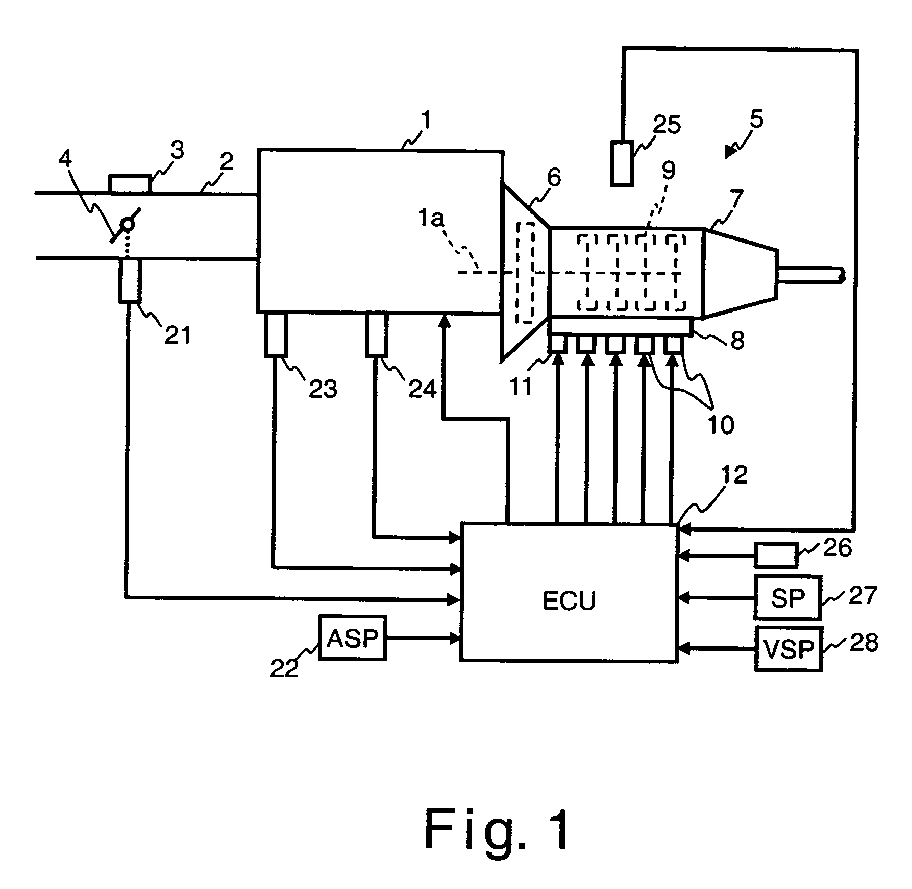
[0018]Referring initially to FIG. 1, an internal combustion engine 1 is schematically illustrated that is equipped with an engine torque control device or system in accordance with one embodiment of the present invention. In FIG. 1, the engine 1 receives intake air through an air intake passage 2 such that the intake air is supplied to each cylinder of the engine 1. The intake air passing through the air intake passage 2 to each cylinder is regulated by controlling a throttle motor 3 that operates a throttle valve 4. The operation of the throttle valve 4 by the throttle motor 3 can be accomplished ...


PUM


Abstract

An engine torque control device is configured to lessen shift shock while shortening the shift time during downshifting with an automatic transmission. When a downshift requirement is generated, a disengagement control of a higher gear clutch (current gear ratio) is commenced, and at the same time, a first synchronizing control is commenced. The first synchronizing control has a torque-up control with a first synchronizing speed DNe1 set as the target speed TNe, during a first control period. When the first control period has concluded and there is a transition to a second control period. In the second control period, an engagement control of a lower gear clutch (the post-shift gear ratio) is commenced, and at the same time, there is a switch to a second synchronizing control. In the second synchronizing control, the target speed TNe is set to a second synchronizing speed DNe2 at the post-shift gear ratio.

Description

CROSS-REFERENCE TO RELATED APPLICATIONS[0001]This application claims priority under 35 U.S.C. § 119 to Japanese Patent Application No. 2004-298135. The entire disclosure of Japanese Patent Application No. 2004-298135 is hereby incorporated herein by reference.BACKGROUND OF THE INVENTION[0002]1. Field of the Invention[0003]The present invention relates to an engine torque control device that controls engine output during the shifting of an automatic transmission to shorten the shift time and reduce shift shock.[0004]2. Background Information[0005]There is a known technique with which shift shock is reduced by performing a shift only after engine output torque has been increased during the downshifting of an automatic transmission having a stepped shifting mechanism, thereby bringing the engine speed closer to the post-downshift speed (see for example, Japanese Laid-Open Patent Publication No. 5-229363).[0006]In view of the above, it will be apparent to those skilled in the art from t...

Claims


Application Information

Patent Timeline
Patent Type & Authority Patents(United States)
IPC IPC(8): B60W10/04F16H61/04B60W10/06B60W10/10B60W10/11F02D29/00F02D45/00F16H59/42F16H59/44F16H59/70F16H61/68F16H61/684F16H63/40F16H63/50
CPCB60W10/06B60W30/19F16H61/0403F16H63/502Y10T477/675Y10T477/677Y10T477/6937B60W30/188B60W10/11
Inventor IRIYAMA, MASAHIROMAEKAWA, TAKUYA
Owner NISSAN MOTOR CO LTD
Why Eureka
Try Eureka