
Radiographic image conversion panel for mammography and method of manufacturing the same

a technology of radiographic image and conversion panel, which is applied in the direction of optical radiation measurement, fluorescence/phosphorescence, instruments, etc., can solve the problems of deterioration of sharpness of reproduced images or the like, low productivity, and complicated manufacturing processes, so as to reduce the distance from the stimulable phosphor layer, improve the quality of image recording, and improve the effect of moisture resistan

Inactive Publication Date: 2008-08-26
FUJIFILM CORP +1
View PDF11 Cites 3 Cited by
  • Summary
  • Abstract
  • Description
  • Claims
  • Application Information

AI Technical Summary

Benefits of technology

[0022]The present invention has been made to solve the above-described problems of prior art, and an object of the present invention is therefore to provide a highly productive radiographic image conversion panel for mammography that secures a large enough image-forming area to photograph the chest wall and that can avoid degradation of characteristics of a stimulable phosphor layer caused by moisture absorption.
[0033]In a radiographic image conversion panel for mammography according to the first and second aspects of the present invention, a stimulable phosphor layer is positioned on a substrate, which has two pairs of two parallel sides, the pair of the first (e.g. longer) sides being referred to as first pair whereas the pair of the second (e.g. shorter) sides being referred to as second pair, such that the distance from a first (e.g. longer) end of the stimulable phosphor layer to at least one of the first sides of the first pair of parallel sides is not long enough to provide a predetermined level of moisture-proof effect when a moisture-proof protective film is bonded to the substrate through a seal bonding layer, the distance being referred to as a first distance, and such that the distance from the second (e.g. shorter) ends of the stimulable phosphor layer to the two sides of the second pair of parallel sides is long enough to provide a predetermined level of moisture-proof effect when the moisture-proof protective film is bonded through the seal bonding layer, the distance being referred to as a second distance, the second distance being larger than the first distance, and the seal bonding layer is formed in areas of the second distance along the perimeter of the stimulable phosphor layer, and is formed on side faces having the first sides of the substrate or on a rear face of the substrate. This makes it possible to reduce the distance from the stimulable phosphor layer to the longer side faces of the substrate. Accordingly, a large enough image-forming area necessary to photograph the chest wall is secured. Furthermore, since an area where a predetermined level of moisture-proof effect is obtained is provided on each side of the stimulable phosphor layer, degradation of image recording characteristics due to moisture absorption can be avoided for a long period of time even under severe conditions created by high temperature and high humidity.
[0034]Moreover, a satisfactory moisture-proof property is obtained by merely bonding the perimeter of the moisture-proof protective film to side faces or bottom face of the substrate through the seal bonding layer, without needing any special member, even in the case where the distance from the stimulable phosphor layer to a longer side face of the substrate is too short for the moisture-proof protective film to provide a predetermined level of moisture-proof effect when bonded to the substrate. A radiographic image conversion panel of the present invention can therefore be manufactured easily at high productivity. The productivity can be further raised if a roll-like moisture-proof protective film is employed.
[0035]Further, in a method of manufacturing a radiographic image conversion panel for mammography according to the third and fourth aspects of the present invention, a stimulable phosphor layer is positioned on a substrate, which has two pairs of two parallel sides, the pair of the first (e.g. longer) sides being referred to as first pair whereas the pair of the second (e.g. shorter) sides being referred to as second pair, such that the distance from a first (e.g. longer) end of the stimulable phosphor layer to at least one of the first sides of the first pair of parallel sides is not long enough to provide a predetermined level of moisture-proof effect when a moisture-proof protective film is bonded to the substrate through a seal bonding layer, the distance being referred to as a first distance, and such that the distance from the second (e.g. shorter) ends of the stimulable phosphor layer to the two sides of the second pair of parallel sides is long enough to provide a predetermined level of moisture-proof effect when the moisture-proof protective film is bonded through the seal bonding layer, the distance being referred to as a second distance, the second distance being larger than the first distance, and the seal bonding layer is formed in areas of the second distance along the perimeter of the stimulable phosphor layer, and is formed on side faces having the first sides of the substrate or on a rear face of the substrate. This makes it possible to reduce the distance from the stimulable phosphor layer to the longer side faces of the substrate. Accordingly, a large enough image-forming area necessary to photograph the chest wall is secured. Furthermore, since an area where a predetermined level of moisture-proof effect is obtained is provided on each side of the stimulable phosphor layer, degradation of image recording characteristics due to moisture absorption can be avoided for a long period of time even under severe conditions created by high temperature and high humidity.
[0036]Moreover, a satisfactory moisture-proof property is obtained by merely bonding the perimeter of the moisture-proof protective film to side faces or bottom face of the substrate with an adhesive, without needing any special member, even in the case where the distance from the stimulable phosphor layer to a longer side face of the substrate is too short for the moisture-proof protective film to provide a predetermined level of moisture-proof effect when bonded to the substrate. A radiographic image conversion panel of the present invention can therefore be manufactured easily at high productivity. The productivity can be further raised if a roll-like moisture-proof protective film is employed.

Problems solved by technology

As a result, deterioration of sharpness of a reproduced image or the like occurs due to deterioration of photostimulated luminescence characteristics, that is, sensitivity, or deterioration of crystallinity of the stimulable phosphor (destruction of columnar crystals in the case of the alkali halide-based stimulable phosphor having a columnar structure, for example).
The radiographic image conversion panels 100 and 110 disclosed in JP 2003-248093 A and shown in FIGS. 9A and 9B, and FIGS. 10A and 10B both have a problem in that their manufacture processes are complicated, which leads to low productivity and high manufacture cost.
The phosphor screen and phosphor panel of JP 2003-149396 A have a problem in that no image can be formed on the perimeter of the phosphor screen or the phosphor panel, because the phosphor layer is smaller in surface area than the support.
The screen or panel thus fails to secure a large enough image-forming area to photograph the chest wall required for mammography.
Further, an image cannot be formed on the perimeter of the radiographic image conversion panel of JP 2002-71899 A, in which the perimeter is heat sealed and therefore a margin for heat seal is needed.
The screen or panel thus fails to secure a large enough image-forming area to photograph the chest wall required for mammography.

Method used


Image

  • Radiographic image conversion panel for mammography and method of manufacturing the same
  • Radiographic image conversion panel for mammography and method of manufacturing the same
  • Radiographic image conversion panel for mammography and method of manufacturing the same

Examples


first embodiment

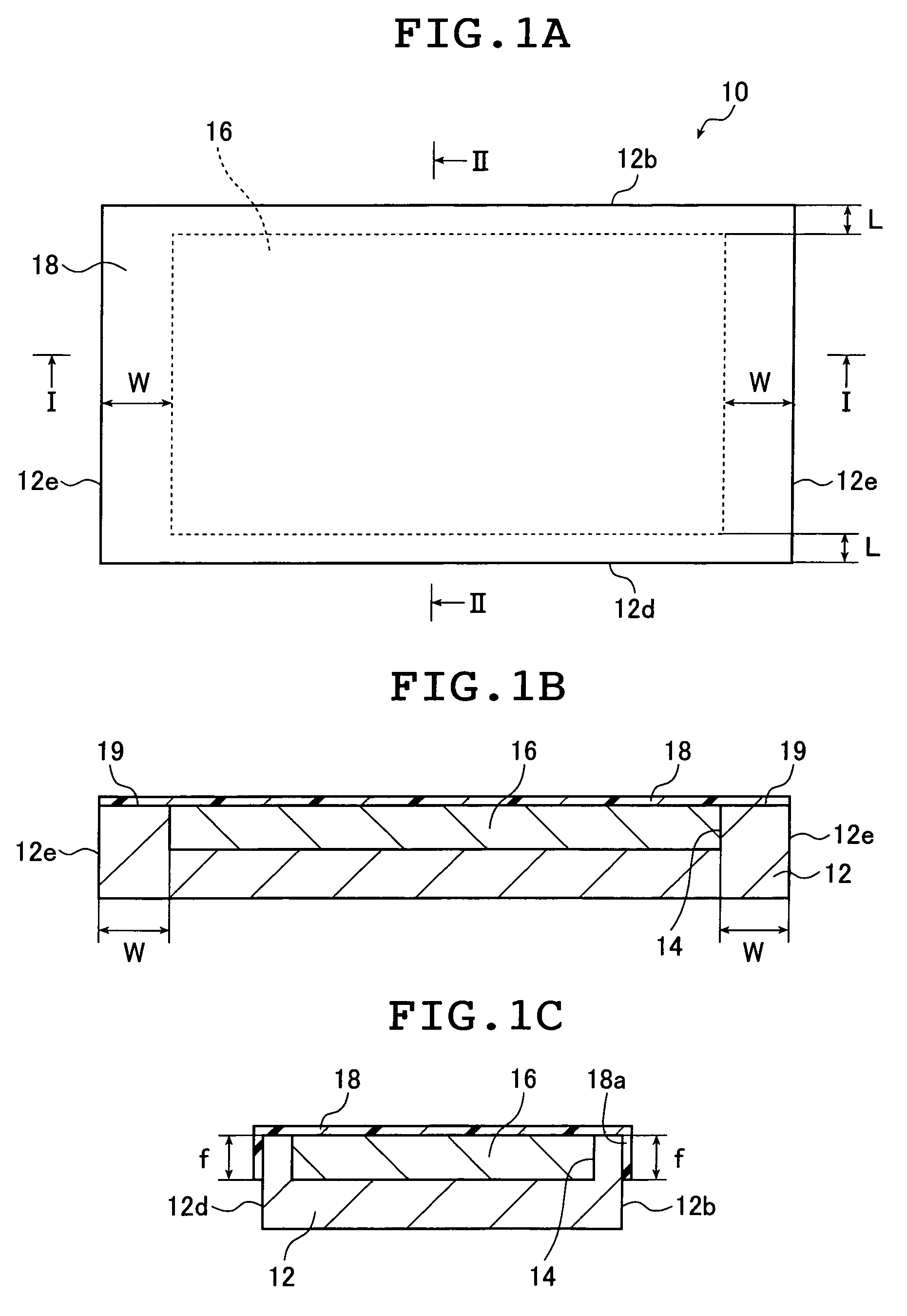
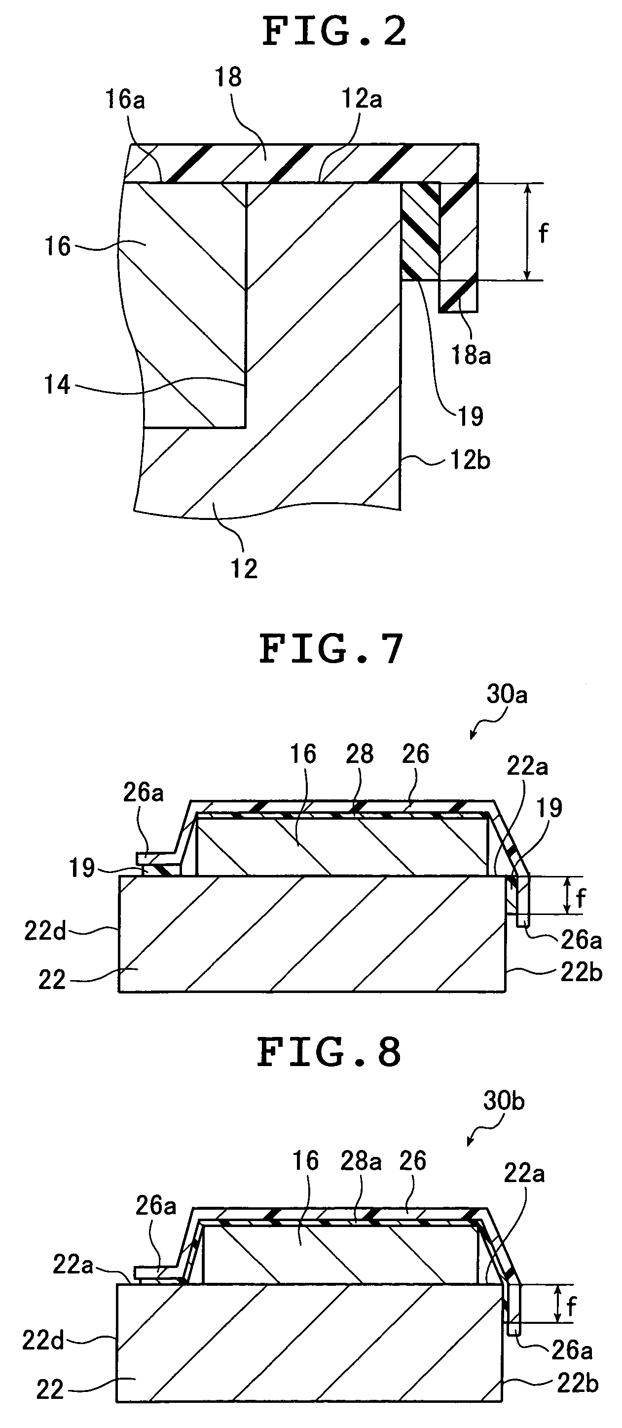
[0057]FIG. 1A is a schematic plan view showing a radiographic image conversion panel for mammography according to the present invention. FIG. 1B is a sectional view taken along the line I-I of FIG. 1A. FIG. 1C is a sectional view taken along the line II-II of FIG. 1A. FIG. 2 is an enlarged view of an essential part of FIG. 1C.

[0058]A radiographic image conversion panel (hereinafter referred to as phosphor panel) 10 for mammography shown in FIG. 1A is used in mammography with a side face 12b which includes one of two longer sides of a substrate 12, or a side face 12d which includes the other of the two longer sides of the substrate 12, facing toward the human body.

[0059]As shown in FIGS. 1A to 1C and FIG. 2, the phosphor panel 10 has the substrate 12, a stimulable phosphor layer (hereinafter referred to as phosphor layer) 16, a moisture-proof protective film 18, and a seal bonding layer 19 which bonds the perimeter of the moisture-proof protective film 18 to the substrate 12. A reces...

second embodiment

[0124]the present invention will be described next.

[0125]FIG. 3A is a schematic plan view showing a radiographic image conversion panel for mammography according to the second embodiment of the present invention. FIG. 3B is a sectional view taken along the line III-III of FIG. 3A. FIG. 3C is a sectional view taken along the line IV-IV of FIG. 3A. FIG. 4 is an enlarged view of an essential part of FIG. 3C.

[0126]In this embodiment, components corresponding to those of the phosphor panel 10 of the first embodiment shown in FIGS. 1A to 1C and FIG. 2 will be denoted by the same reference symbols and numerals, and the detailed description thereof will be omitted.

[0127]A phosphor panel 10a of this embodiment shown in FIGS. 3A to 3C differs from the phosphor panel 10 of the first embodiment (see FIGS. 1A to 1C) in terms of the position where the recess 14 is formed and the position where the moisture-proof protective film 18 is bonded to the substrate 12. The structure of the phosphor panel...

third embodiment

[0143]the present invention will be described next.

[0144]FIG. 5 is a schematic sectional view showing a radiographic image conversion panel for mammography according to the third embodiment of the present invention, and corresponds to the sectional view taken along the line II-II of FIG. 1A. The seal bonding layer 19 is omitted in FIG. 5.

[0145]In this embodiment, components corresponding to those of the phosphor panel 10 of the first embodiment shown in FIGS. 1A to 1C and FIG. 2 will be denoted by the same reference symbols and numerals, and the detailed description thereof will be omitted.

[0146]A phosphor panel 20 of this embodiment differs from the phosphor panel 10 of the first embodiment in that no recess is formed in a substrate 22. The recess 14 is replaced by, for example, as shown in FIG. 5, a frame (sealing portion) 24 formed on a front face 22a of the substrate 22. The phosphor layer 16 is formed within the frame 24.

[0147]The frame 24 of this embodiment is formed around th...


PUM

PropertyMeasurementUnit
critical bonding lengthaaaaaaaaaa
distanceaaaaaaaaaa
thicknessaaaaaaaaaa

Abstract

The radiographic image conversion panel for mammography includes a phosphor layer formed on a rectangular substrate having first and second pairs of two parallel sides, and sealed with a moisture-proof protective film. The phosphor layer is positioned on the substrate such that a distance from at least one side of the first pair to an adjacent end of the phosphor layer is shorter than a critical bonding length being a shortest bonding length long enough to provide a predetermined level of moisture-proof effect and distances from two sides of the second pair to adjacent ends of the phosphor layer are not shorter than the critical length. A seal bonding layer is formed in areas of the second distance, and on a side surface having the at least one side or on the side surface and a rear surface of the substrate. The phosphor layer may be formed in a recess formed in the substrate.

Description

[0001]The entire contents of literatures cited in this specification are incorporated herein by reference.BACKGROUND OF THE INVENTION[0002]The present invention relates to a highly productive radiographic image conversion panel for mammography that can secure a large enough image-forming area to photograph the chest wall and that avoids degradation of characteristics due to moisture absorption, and a method of manufacturing the panel.[0003]There are known a class of phosphors which accumulate a portion of applied radiations (e.g. x-rays, α-rays, β-rays, γ-rays, electron beams, and uv (ultraviolet) radiation) and which, upon stimulation by exciting light such as visible light, give off a burst of light emission in proportion to the accumulated energy. Such phosphors called stimulable phosphors are employed in medical and various other applications.[0004]An exemplary application is a radiographic image information recording and reproducing system which employs a radiographic image con...

Claims


Application Information

Patent Timeline
Patent Type & Authority Patents(United States)
IPC IPC(8): G03B42/08G01N21/64G21K4/00G01T1/20
CPCG03B42/04G03B42/02
Inventor HOSOI, YUICHI
Owner FUJIFILM CORP
Learn More