
Ophthalmic aberrometer for measuring aberrations in the eye

a technology of applied in the field of optic aberration measurement and aberration measurement in the eye, can solve the problems of large error of spot center estimation, non-uniformity of retinal reflection, and sh wavefront sensor, so as to improve specificity and improve dynamic range.

Inactive Publication Date: 2008-09-02
KESTREL CORP
View PDF2 Cites 20 Cited by
  • Summary
  • Abstract
  • Description
  • Claims
  • Application Information

AI Technical Summary

Benefits of technology

[0018]Another aspect of the present invention is improved spatial accuracy for aberrations measured.
[0020]Another aspect of the present invention provides an aberrometer with an improved dynamic range.
[0021]Another aspect of the present invention provides an aberrometer with improved specificity.

Problems solved by technology

SH wavefront sensors suffer from problems with intensity modulation that introduce scintillation effects and non uniformity of retinal reflection.
For example, spot shapes on the Hartmannogram are very irregular, which makes the error of estimation of the spots' centers rather large.
However, temporal and spatial errors are introduced into the data with these solutions.
Scatter and scintillation produce amplitude fluctuation in SH lenslet images rendering a wavefront that is known to be inaccurate.
Existing SH wavefront sensors have a narrow dynamic range and suffer from a lack of high sensitivity.
Currently, no wavefront system exists that works well to produce objective data for eyes with scintillation and scatter, over a wide dynamic range, or varying amounts of accommodation.

Method used


Image

  • Ophthalmic aberrometer for measuring aberrations in the eye
  • Ophthalmic aberrometer for measuring aberrations in the eye
  • Ophthalmic aberrometer for measuring aberrations in the eye

Examples


examples

[0063]Referring now to FIG. 8, an image of an eye 863 and pupil 820 as seen through a near infrared detector is illustrated according to one embodiment of the present invention. Pupil diameter as illustrated by the double head arrow. The diameter is a value used for reducing the data and comparing subject data according to one embodiment of the present invention. An infrared light source (not shown) illuminates an eye and the illuminated eye is detected with an infrared detector (not shown). For example, the light source comprises an infrared diode that operates in the short wave infrared, such as at about 900 nm. The wavelength is invisible to the subject but readily observable with an infrared detector such as a CCD type of camera with an objective lens. The diameter of the pupil is determined for example by measuring the number of pixels of the detector across which the pupil diameter spans.

[0064]Referring now to FIG. 9, a reference beam on the retina is illustrated for a static ...


PUM


Abstract

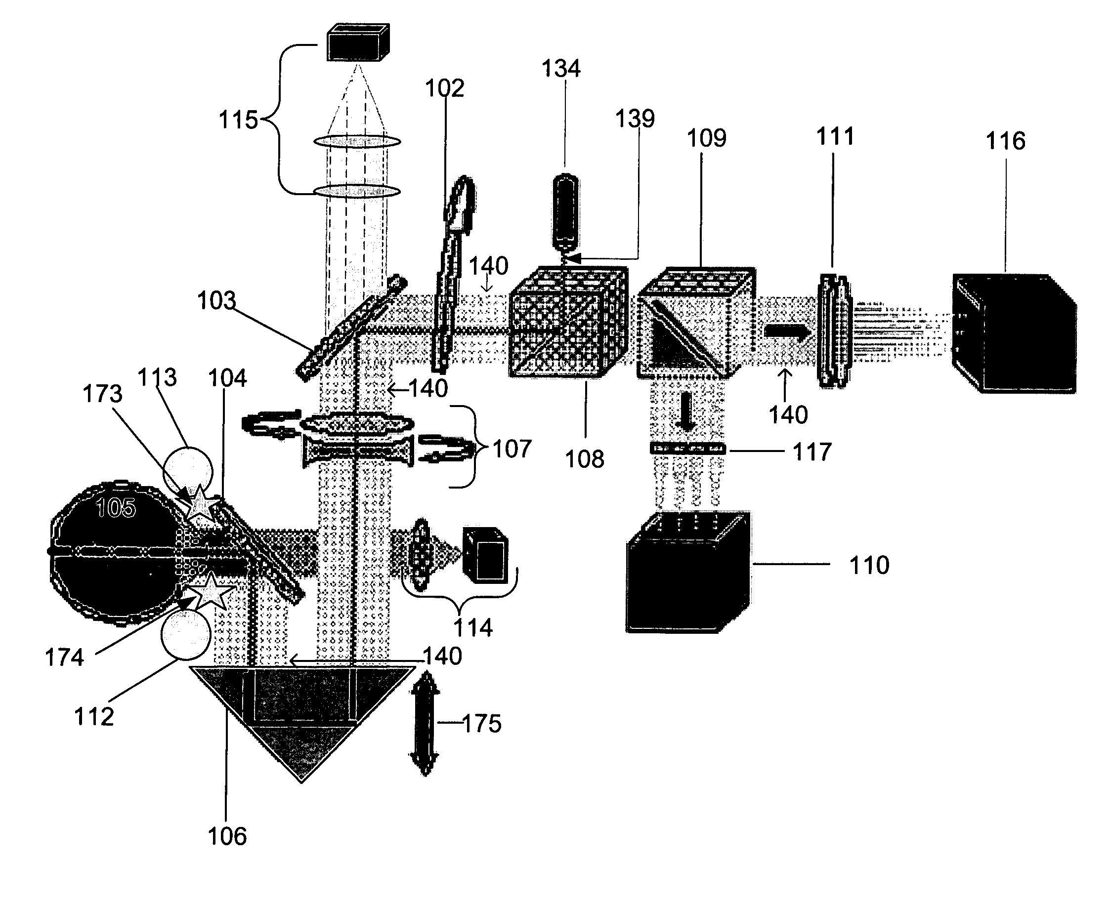
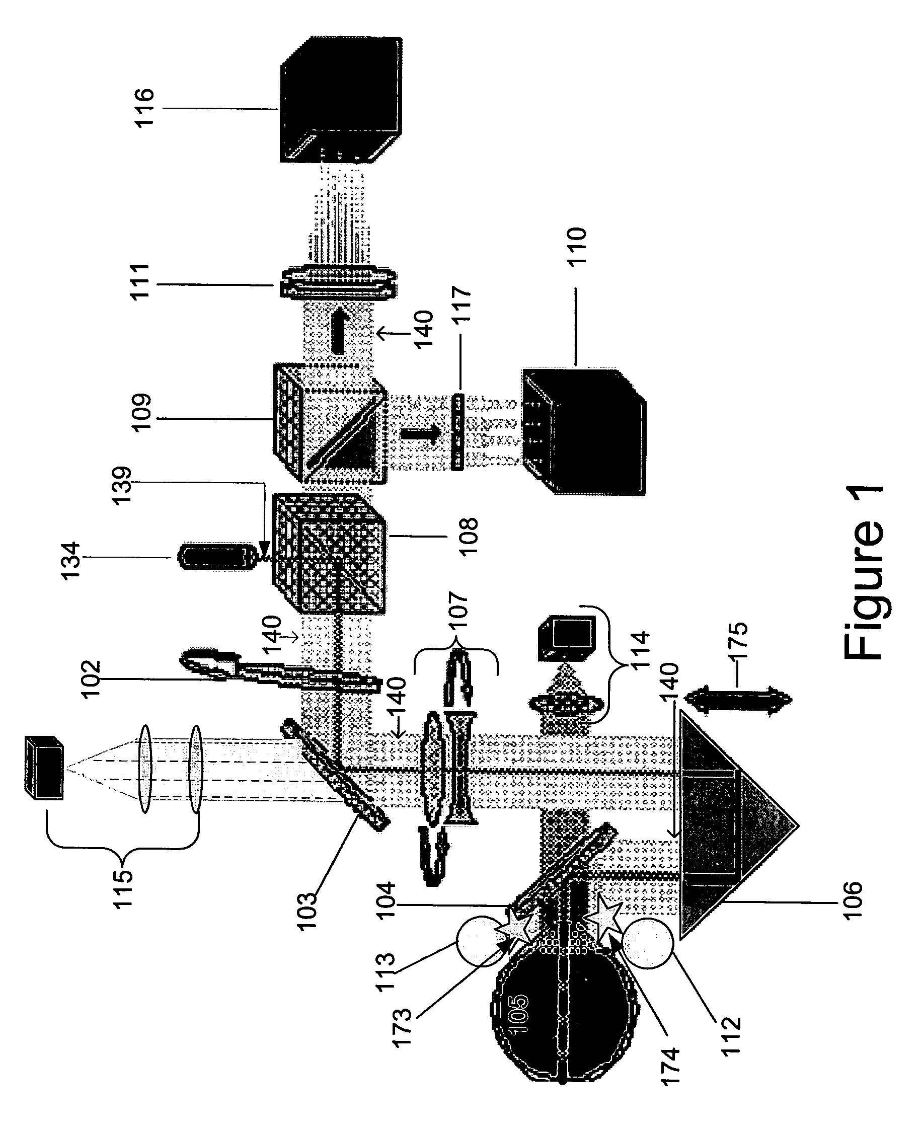
A ophthalmic aberrometer uses a wavefront sensor aligned with an eye under examination through an optical path and a light source for introducing a light beam into the eye via the optical path, wherein the optical path has a reference through which the light beam passes before passing to an eye retina to form a reference spot on the retina, a focus dynamic range extender, and an astigmatism dynamic range extender positioned in the optical path between the reference and an eye under examination. The wavefront sensor is positioned to receive a wavefront reflected from the eye retina via the optical path.

Description

CROSS REFERENCE TO OTHER APPLICATIONS[0001]This application claims benefit under 35 U.S.C. § 119(e) of provisional application No. 60 / 518,274, filed Nov. 7, 2003, which is incorporated by reference herein, in its entirety, for all purposes.STATEMENT REGARDING GOVERNMENT INTEREST[0002]This invention was made with government support under Contract No. 2R44EY12174-02, Contract No. 1R43EY014493-01A1 and Contract No. 1 R43 EY014518-01 awarded by the National Eye Institute. The government has certain rights in the invention.FIELD OF THE INVENTION[0003]The present invention relates to a novel opthalmic aberrometer and method for measuring aberrations in an eye.BACKGROUND ART[0004]A human eye is subject to a variety of optical aberrations. Accurate measurement of optical aberrations is essential for precise correction by customized photo-refractive surgery, by use of customized contact lenses, or by use of customized intra-ocular lenses. Wavefront measurement is a commonly used method to de...

Claims


Application Information

Patent Timeline
IPC IPC(8): A61B3/14
CPCA61B3/1015
Inventor OTTEN, III, LEONARD JOHNHARRISON, PAULERRY, GAVIN
Owner KESTREL CORP
Learn More