Pump valve mechanism

a technology of pump valve and valve body, which is applied in the direction of cleaning equipment, lighting and heating apparatus, cleaning using liquids, etc., can solve the problems of reducing the heat transfer capacity of material which may coat the interior of the tube, affecting the cleaning effect, and periodically interrupting the operation, etc., to achieve the effect of quick sealing

Inactive Publication Date: 2008-09-09
AIMM TECH
View PDF7 Cites 19 Cited by
  • Summary
  • Abstract
  • Description
  • Claims
  • Application Information

AI Technical Summary

Benefits of technology

[0011]When the lance is inserted, the tip of the lance is placed in the particular tube to be cleaned. Hydraulic control enables rapid indexing of the lance to the left and right to align with the proper tube and to insert into that tube once alignment has been accomplished. The tip of the lance is profiled so that it forms a fairly quick seal with the end of the tube. The lance is hollow to deliver liquid through the end of the lance into the tube. A pressurized air supply provides air to the pump / valve mechanism to purge the tube to be cleaned to set the tube up for a water hammer action when the lance is pressurized with water or cleaning solution.

Problems solved by technology

However, such continuous operation may be periodically interrupted to clean the tubes.
The cleaning process is necessary to remove residue which collects on the inside surface of the tubes which reduces their heat transfer capability.
The material which may coat the interior of the tubes, however, has a much lower thermal efficiency for heat transfer.
Therefore, the coating formed on the interior of the tubes is detrimental to the efficiency of the operation of the heat exchanger.
As residue builds up on the inside surface of a heat exchanger tube, the tube becomes less and less efficient.
However, there are limits to this solution.
For instance, the metal used in the tubes of the heat exchanger has a limited capacity for heat as a result of metallurgical considerations.
Exceeding the design temperature differential across through the tubes increases fatigue and therefore reduces the useful lifetime of the heat exchanger.
Cleaning the tubes involves removing the accumulated coating material on the inside of the tubes and the difficulty of cleaning the inside surfaces of the tubes is exacerbated by the bend in the tubes.
This makes the task of cleaning the tubes more difficult because the long and relatively narrow tubes do not permit easy access to the tubes.
That is successful but it has limitations.
For particularly stubborn and tenacious fowling, especially involving hundreds of tubes, this manual alignment of the control panel valves can become tiresome and tedious.

Method used


Image

  • Pump valve mechanism
  • Pump valve mechanism
  • Pump valve mechanism

Examples


Embodiment Construction

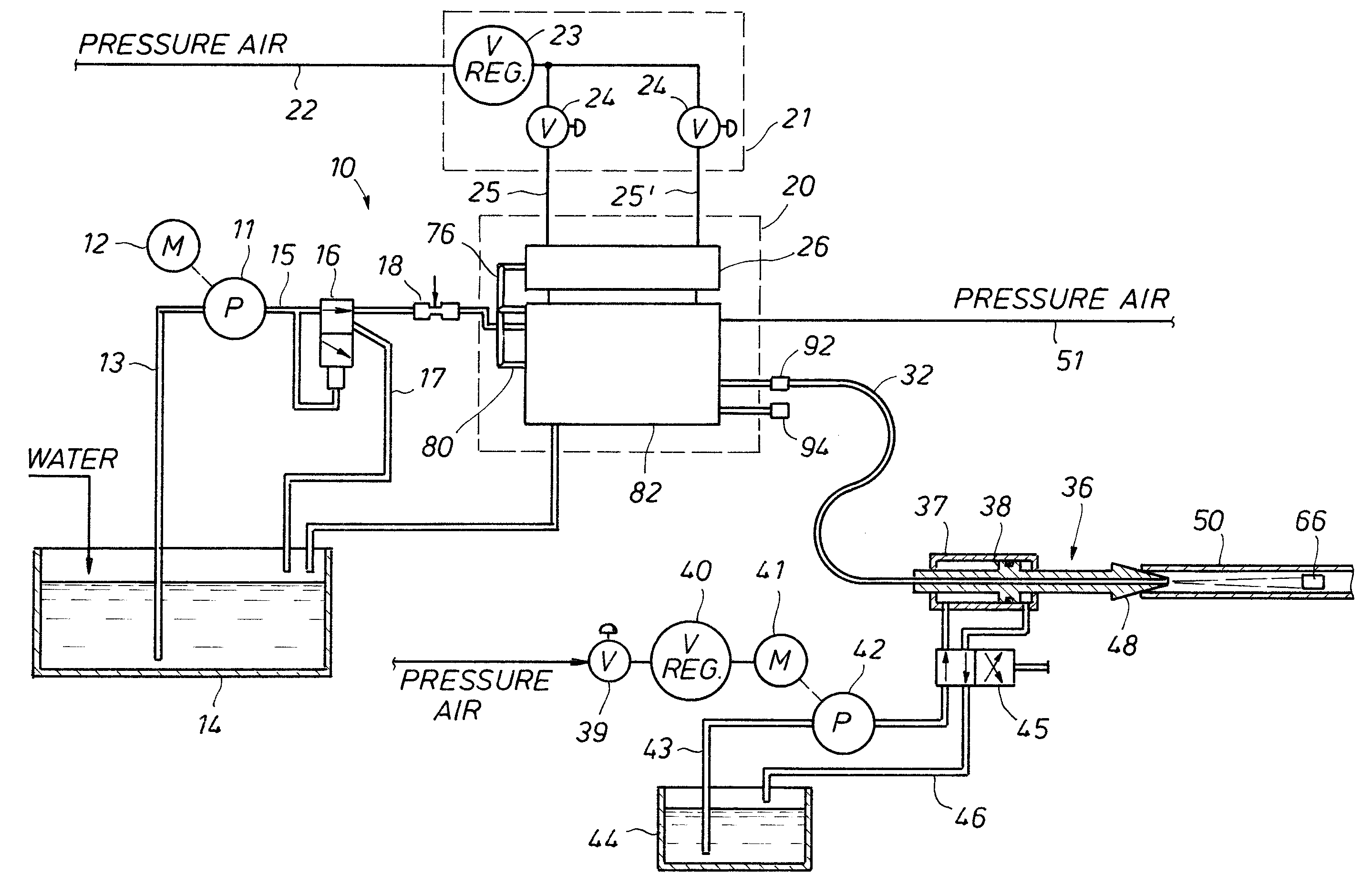
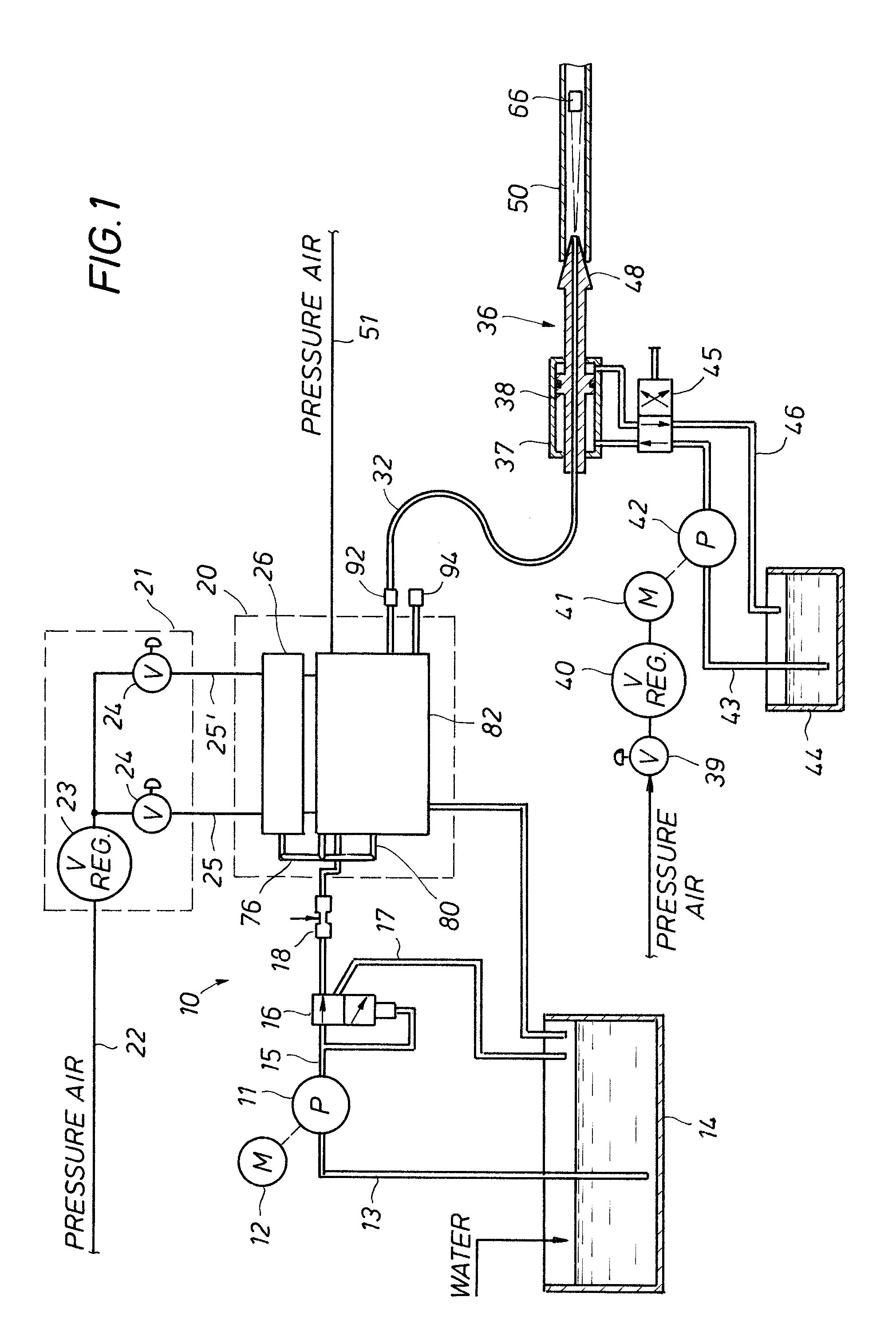
[0021]Attention is now directed to FIG. 1 of the drawings which illustrates a schematic of a system 10 for cleaning tubes and the like. The system includes a pump 11 driven by a suitable motor 12 of substantial power. The pump 11 takes a suction through a feed line 13 from a water sump or reservoir 14. Water level is maintained in the sump by occasional replenishment. Moreover, the water is typically pure but it can be used with additives. For instance, certain types of acids or bases can be added to accomplish chemical attack on the material to be removed.

[0022]The pump 11 has a pump output 15 which is provided to a control valve 16. The control valve 16 is a two position valve. In the illustrated position, water under pressure is delivered from the pump through an adjustable orifice 18. Alternatively, the valve 16 connects with a line 17 which provides a return to the sump. The orifice 18 provides a control signal to manifold 20 of a pump valve mechanism represented in phantom in ...


PUM


Abstract

A method for cleaning tubes and heat exchangers provides an oscillating pump / valve mechanism to provide a periodic waveform of shocks to fouled tubes. Preferably, a pair of pneumatic control valves operates an actuator to oscillate a valve within a valve block, and isolation of a fluid within a manifold in the block creates a pumping action from the valve, to create an intense fluid shock wave to clean interior surfaces tubes.

Description

FIELD OF THE INVENTION[0001]The present invention relates generally to the field of devices for cleaning clogged heat exchanger tubes and, more particularly to a system for cleaning tubes within a vessel using a pump valve mechanism for mechanically applying variable pressure to material clogging the tubes.BACKGROUND OF THE INVENTION[0002]A heat exchanger is normally formed of a plurality of tubes oriented generally parallel to one another. In normal operation, a fluid to be heated or cooled is delivered through the inside of the tubes of such a heat exchanger. The outside surface of the tubes are contacted with a fluid which adds heat or removes heat as required. The plurality of generally parallel tubes forms a bundle. A set of end plates, known as heads, commonly support the bundle of tubes at each end.[0003]Heat exchangers usually operate in a continuous fashion, often for months at a time. However, such continuous operation may be periodically interrupted to clean the tubes. Th...

Claims


Application Information

Patent Timeline
Patent Type & Authority Patents(United States)
IPC IPC(8): A47L15/00
CPCB08B9/032F28G7/00B08B9/0321B05B1/083
Inventor GARCIA, JR., RALPH
Owner AIMM TECH
Why Eureka
Try Eureka