Steam engine

a steam engine and steam technology, applied in the field of steam engines, can solve the problems of inability to increase the fluid pressure by vaporization, the output energy of steam engines would be smaller, and the heat transfer time for transferring heat from the inner surface of the cooling portion to the center of the working fluid becomes longer, so as to prevent the effect of mechanical energy reduction

Inactive Publication Date: 2008-09-16
DENSO CORP
View PDF5 Cites 12 Cited by
  • Summary
  • Abstract
  • Description
  • Claims
  • Application Information

AI Technical Summary

Benefits of technology

[0027]The present invention is made in view of the above problems. It is an object of the present invention to provide a steam engine, in which working fluid in a fluid container is vibrated in an appropriate vibrating manner as a result of a repeated operation of vaporization and liquefaction of the working fluid, to prevent a decrease of output mechanical energy.
[0028]It is a further object of the present invention to provide a steam engine, in which energy transfer effectiveness is improved to increase the output mechanical energy.
[0029]It is a still further object of the present invention to provide a steam engine, in which heating and cooling efficiency are increased.

Problems solved by technology

(1) At first, output energy of the steam engine would become smaller, when a cross sectional area of a cooling portion of the fluid container, at which the steam of the working fluid is liquefied, is not properly designed.
On the other hand, in the case that a cross sectional area of the cooling portion of the fluid container is made extremely large, the heat transfer time for transferring the heat from the inner surface of the cooling portion to the center of the working fluid, becomes longer.
As a result, the fluid pressure by the vaporization can not be increased, and thereby the operation of the steam engine may be irregularly stopped.
It is, however, inevitably necessary, in the above method of increasing the temperature at the heating device and decreasing the temperature of the cooling device, to increase the input energy to the heating and cooling devices.
The output mechanical energy obtained by the steam engine is thereby increased on one hand, but energy loss would be adversely become larger on the other hand, if energy transfer effectiveness from the heat energy to the mechanical energy is low.
The heating efficiency and cooling efficiency at the respective heating and cooling portions are thereby decreased, so that the energy transfer effectiveness can not be sufficiently improved.
As a result, the mechanical energy can not be sufficiently generated at the steam engine.
It is, however, a problem in such steam engine that the heating efficiency is not sufficiently high.
Therefore, the steam engine of this kind has a larger heat loss.

Method used


Image

  • Steam engine
  • Steam engine
  • Steam engine

Examples


first embodiment

[0065]A first embodiment of the present invention will now be explained with reference to the drawings.

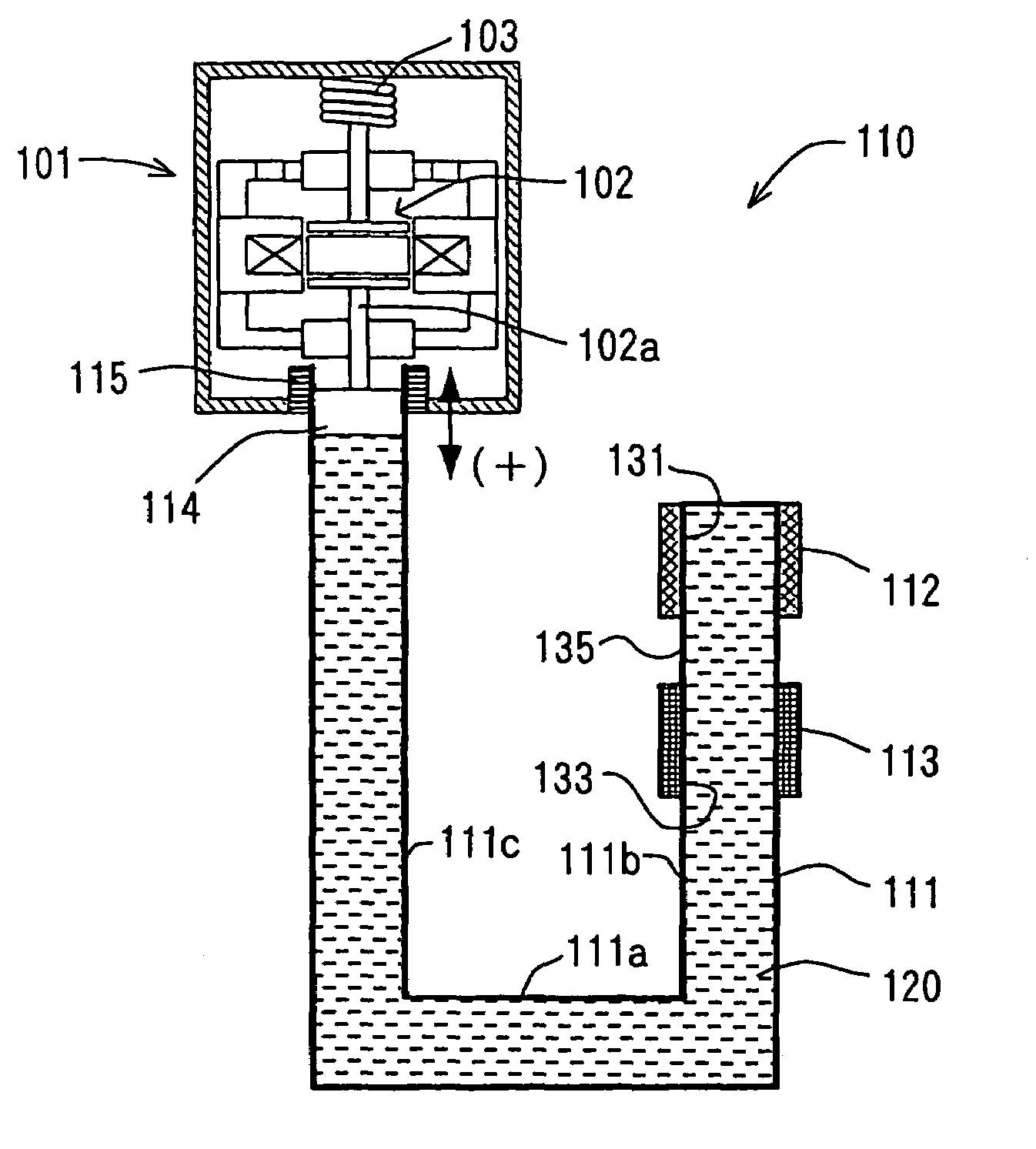
[0066]In the first embodiment shown in FIG. 1, a steam engine 110 is applied to a linear motor, in which a moving member 102 of an output device (an electric power generator) 101 is vibrated. An electric power device comprises the steam engine 110 and the electric power generator 101.

[0067]The electric power generator 101 is a linear vibration generator, in which a permanent magnet (not shown) is fixed to the moving member 102 and electromotive force is generated by vibrating (oscillating) the moving member 102.

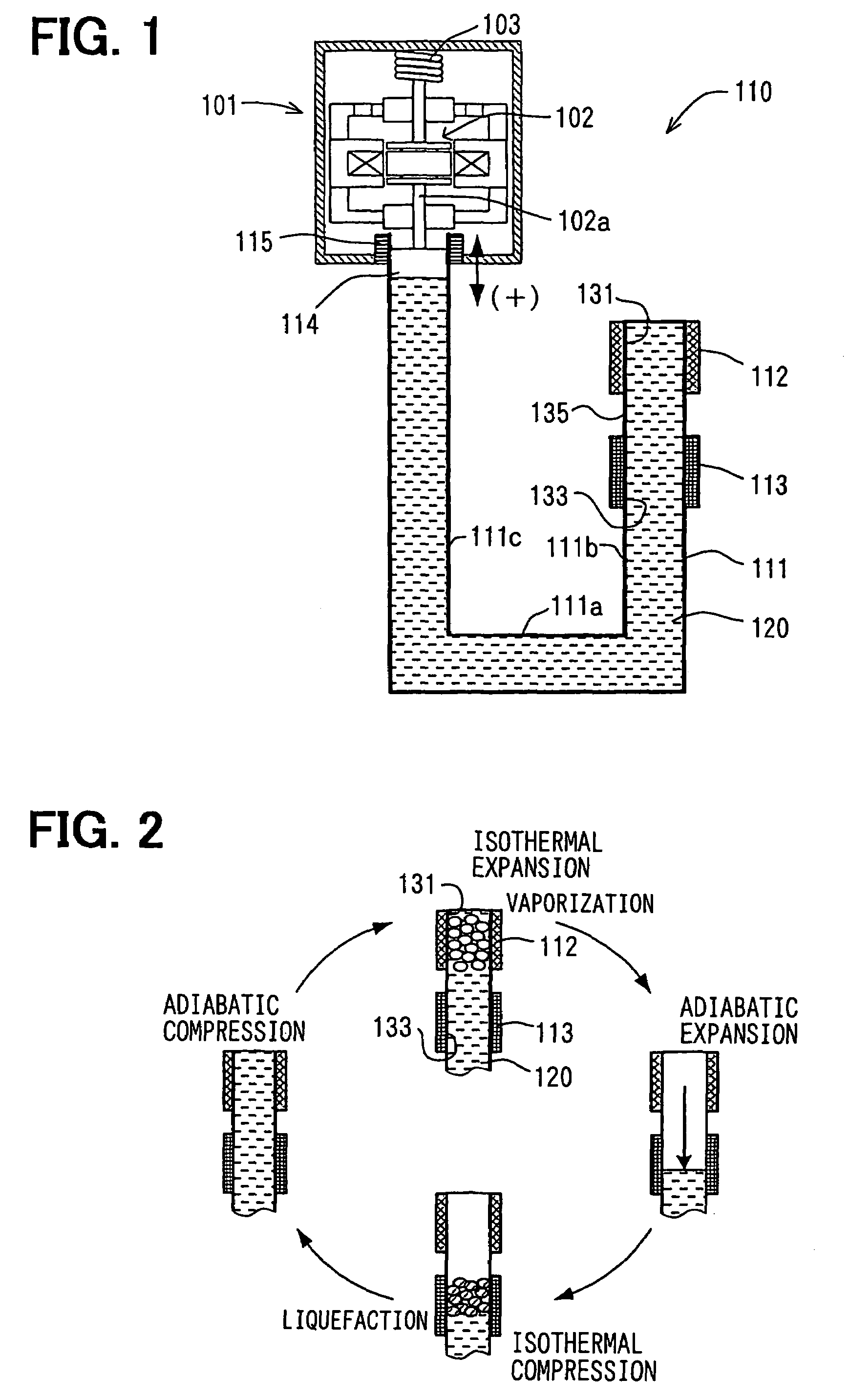
[0068]As shown in FIG. 1, the steam engine 110 comprises a fluid container 111 in which working fluid 120 is filled with a predetermined pressure, a heating device 112 for heating the working fluid 120 in the fluid container 111, and a cooling device 113 for cooling down steam generated at the heating device 112.

[0069]The heating device 112 and the cooling device 113 are arr...

second embodiment

[0112]A second embodiment of the present invention is explained with reference to FIGS. 6 to 9, wherein the same reference numerals are used to designate the same or similar portions of the first embodiment.

[0113]In FIG. 6, a heating portion 131, a connecting portion 135 and a cooling portion 133 of a first straight pipe portion 111b are formed from multiple small pipe portions 215, and a lower part of the first straight pipe portion 111b is formed from a collecting pipe portion 216. Each of the lower ends of the small pipe portions 215 is communicated with the collecting pipe portion 216, whereas each of the upper ends of the small pipe portions 215 is closed.

[0114]A heating device 112 and a cooling device 113 are respectively formed to surround the heating portion 131 and the cooling portion 133 of the multiple small pipe portions 215.

[0115]FIG. 7 schematically shows an enlarged cross sectional view of the heating and cooling devices 112 and 113, wherein liquid surfaces of working...

third embodiment

[0138]The steam engine 110 according to a third embodiment, in which a communication portion 243 is provided to communicate the small pipe portions 215 with one another, is explained with reference to FIG. 10.

[0139]The steam engine 110 differs from the second embodiment (FIGS. 6 to 8) in a structure of a top end portion of the first straight pipe portion 111b.

[0140]A cross sectional view of the top end portion of the first straight pipe portion 111b, the heating device 112, and the cooling device 113 is shown in FIG. 10, wherein the liquid-phase working fluid 120 is pushed down by the fluid pressure of the steam in the fluid container 111.

[0141]As shown in FIG. 10, the communication portion 243 is formed at the top end of the fluid container 111 to communicat the small pipe portions 215 (at upper ends of the heating portions 131) with one another, so that an inside space of the communication portion 243 is communicated with all of the inside spaces of the small pipe portions 215.

[0...


PUM


Abstract

A steam engine has a pipe shaped fluid container, a heating and cooling devices respectively provided at a heating and cooling portions of the fluid container, and an output device connected to the fluid container, so that the output device is operated by the fluid pressure change in the fluid container, to generate an electric power. In such a steam engine, an inner radius “r1” of the cooling portion is made to almost equal to a depth “δ1” of thermal penetration, which is calculated by the following formula (1);δ1=2⁢a1ω(1)wherein, “a1” is a heat diffusivity of the working fluid at its low pressure, and “ω” is an angular frequency of the movement of the working fluid.

Description

CROSS REFERENCE TO RELATED APPLICATION[0001]This application is based on Japanese Patent Application Nos. 2004-149599, 2004-149600, and 2004-149601, each of which is filed on May 19, 2004, the disclosures of which are incorporated herein by reference.FIELD OF THE INVENTION[0002]The present invention relates to a steam engine having a fluid container, in which working fluid is filled and the working fluid is vibrated in the fluid container in a self-excited vibrating manner as a result of a repeated operation of vaporization and liquefaction of the working fluid by heating and cooling the working fluid. A mechanical energy is generated at an output device of the steam engine, which is operated by the fluid vibration in the fluid container.BACKGROUND OF THE INVENTION[0003]An apparatus for a steam engine is known in the art, for example as disclosed in Japanese Patent Publication No. S58-057014, in which working fluid is filled in a fluid container, the working fluid is heated and vapo...

Claims


Application Information

Patent Timeline
Patent Type & Authority Patents(United States)
IPC IPC(8): F01B1/00F01K13/00F01K1/00F01K23/04F01K27/00
CPCF01K27/005
Inventor YATSUZUKA, SHINICHIODA, SHUZOHAGIWARA, YASUMASAMORISHITA, TOSHIYUKIKOMAKI, KATSUYA
Owner DENSO CORP
Why Eureka
Try Eureka