Mortarboard

a mortar board and masonry technology, applied in the field of mortar board configuration, can solve the problems of affecting the retention of materials, affecting the use of mortar boxes, troughs and bowls, and prone to fracture and splinter, and achieve the effects of reducing bonding, enhancing retention of materials, and being light and durabl

Active Publication Date: 2008-09-16
CARNEY BRIAN P
View PDF13 Cites 4 Cited by
  • Summary
  • Abstract
  • Description
  • Claims
  • Application Information

AI Technical Summary

Benefits of technology

[0009]The present invention provides an improved mortarboard configuration that is lightweight and durable and which has an upper polymer surface that reduces bonding of cement, mortar and similar products (both cementitious and acrylic based) thereto, providing ready cleaning of the mortarboards without damage to the surface. In a preferred configuration of the invention, the upper surface of the mortarboard is continuously contoured or dished to enhance retention of the material carried thereby and any water or other liquid used for retempering the material, and to provide for improved material workability. The contoured surface also reduces sliding frictional contact between the mason's applicator tool such as a trowel, and the surface area, and enhances the material removal process from the mortarboard surface without excessive resistance or loss of material.

Problems solved by technology

Further, known mortar box, pail, trough and bowl structures can be difficult to use since the mason must generally dig down into the mortar or other material, to lift it out of such structures.
Wooden mortarboards, such as those made simply by cutting a section from a piece of plywood, have a tendency to fracture and splinter, and absorb water with use, subjecting them to rot.
As they absorb water, they also increase in weight and become more difficult to move.
Those mortarboards made from steel have a tendency to rust and are subject to denting or deformation if struck by a hammer or the like to remove unwanted dried material that may adhere to their surfaces.
Known existing mortarboards are fairly heavy, making it more difficult to move a plurality of such devices from place to place.
Such escapement makes it more difficult to mix or retemper materials carried by the mortarboard.
Such lip, however, can impose an obstacle to the mason's applicator tool as he sweeps or swipes the mortar or other material from the surface of the mortarboard.

Method used


Image

  • Mortarboard
  • Mortarboard
  • Mortarboard

Examples


Embodiment Construction

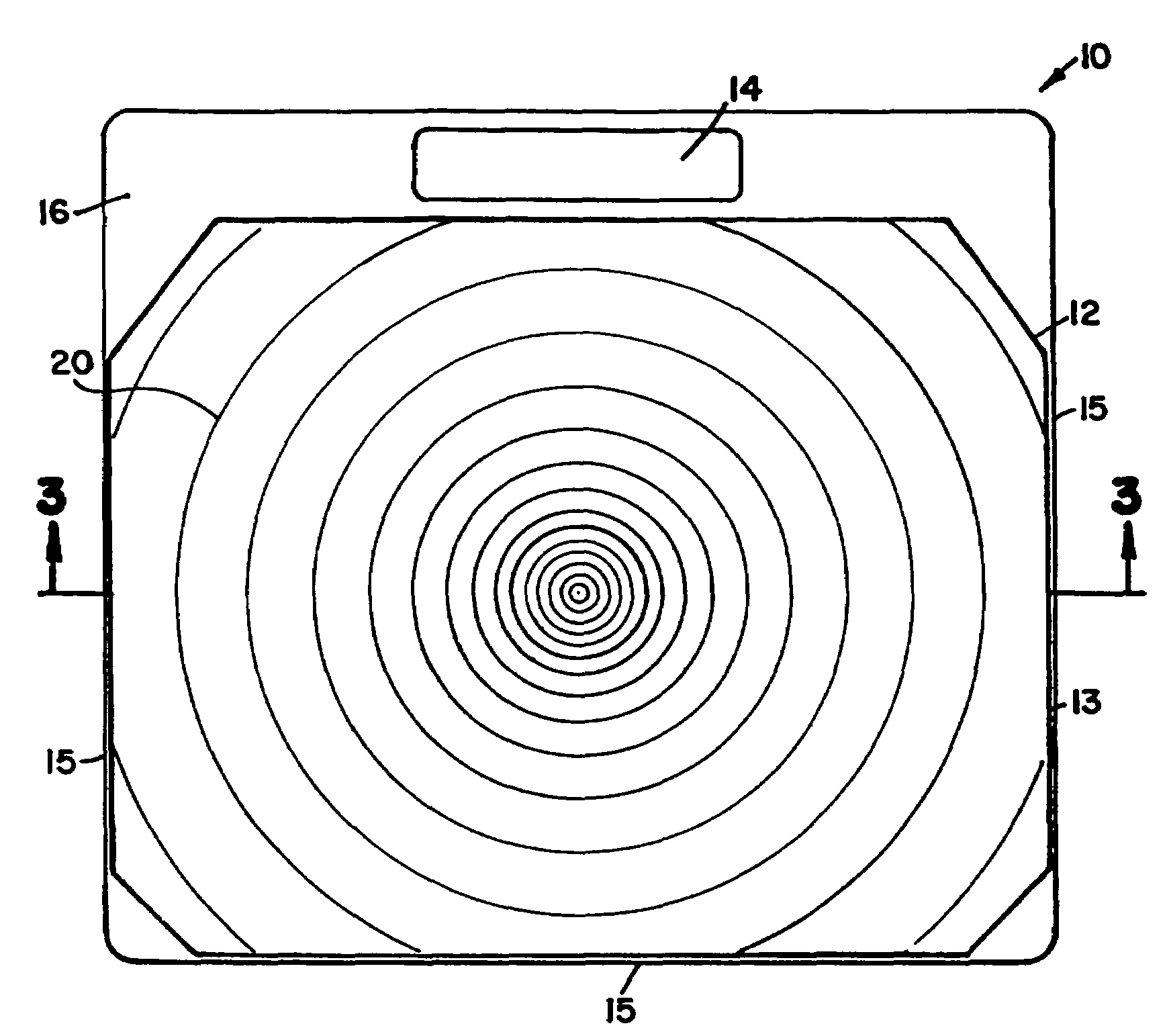
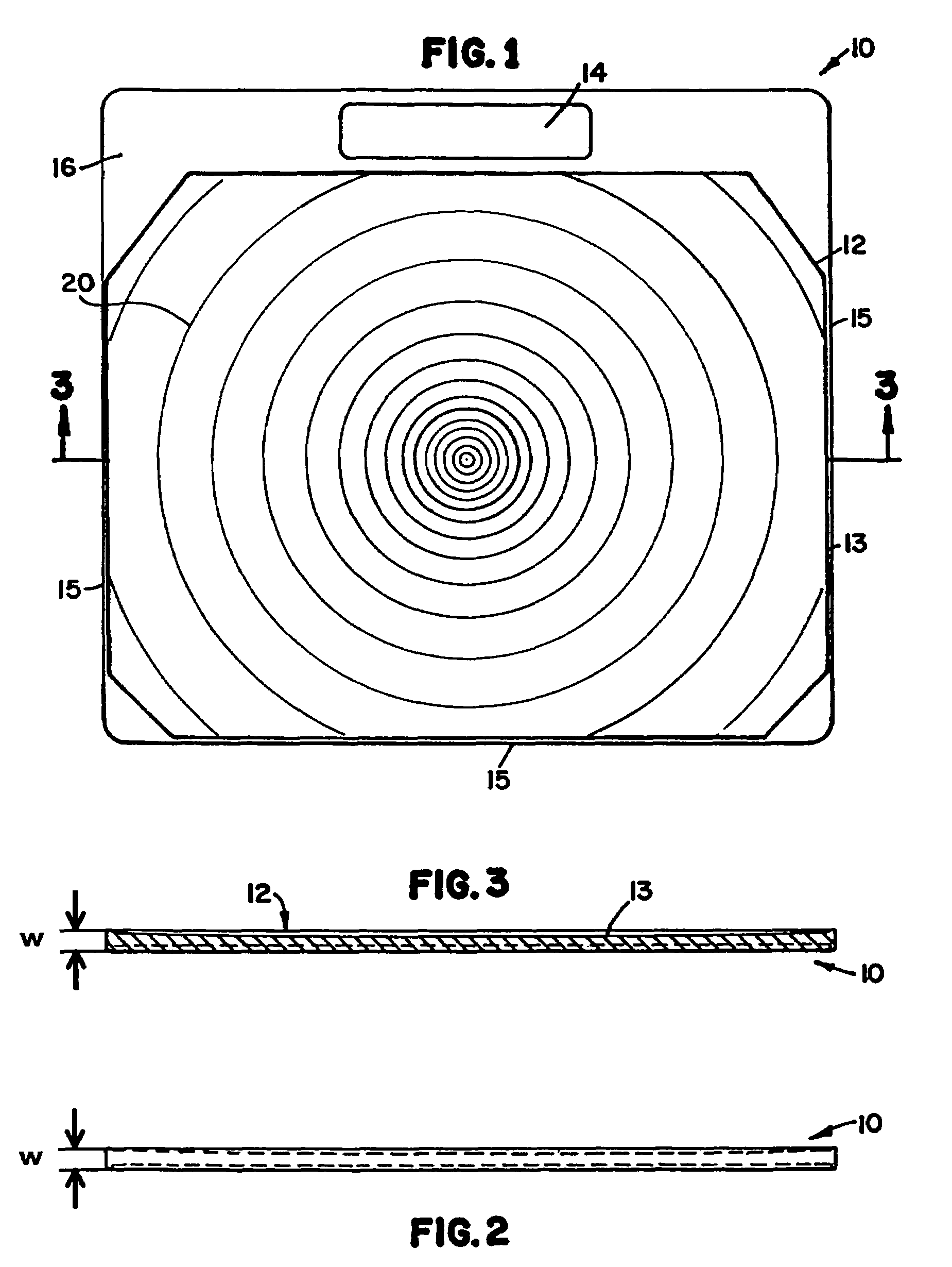
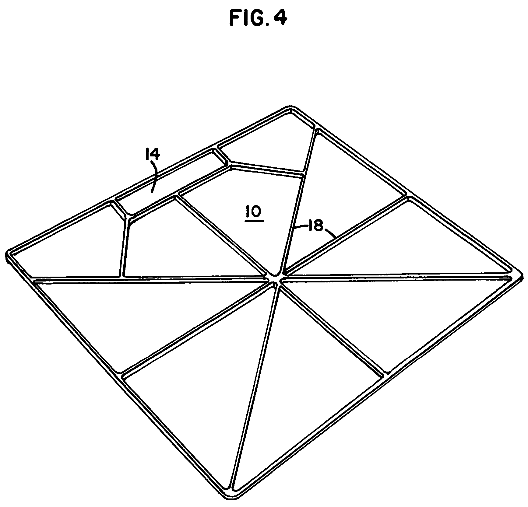
[0024]A first preferred embodiment of the mortarboard apparatus incorporating the principles of this invention is illustrated at 10 in FIGS. 1-4 and FIG. 8. The mortarboard is preferably made from a polymer material such as polyethylene, polypropylene, urethane, nylon, polycarbonate, ABS, PVC, or the like. Such polymers may be lightweighted with a blowing agent such as with nitrogen pellets, to create a structural foam structure, as is well-known in the art. The mortarboard 10 may be formed by known methods of constructing polymer material such as by injection molding, compression molding, roto molding, or other known methods. Such polymer materials provide significant strength, yet are relatively lighter in weight than previously used mortarboard material such as wood, steel or fiberglass. For example, a mortarboard configured as illustrated in the Figures might weigh as little as 5 pounds. Further, as constructed from polymer material, the mortarboard will not absorb water or mois...


PUM


Abstract

The present invention provides an improved mortarboard configuration that is lightweight and durable. In a preferred configuration of the invention, the upper surface of the mortarboard is continuously contoured or dished to enhance retention of the material carried thereby and any water or other liquid used for retempering the material, and to provide for improved material workability. The mortarboard may have a handle to improve portability and handling.

Description

MORTARBOARD[0001]This application claims priority under 35 U.S.C. § 119(e) to U.S. provisional application Ser. No. 60 / 445,658, filed Feb. 7, 2003 and entitled MORTARBOARD. The entire disclosure of 60 / 445,658 is incorporated herein by reference.FIELD OF THE INVENTION[0002]This invention relates generally to masonry products and more particularly to an improved mortarboard configuration.BACKGROUND OF THE INVENTION[0003]Laying and cementing brick, block and stone and the application of plaster and stucco to structural surfaces have been the hallmarks of the masonry trade for many centuries. Since the inception of the masonry trade, some type of a holding member or container has been used to hold a small quantity of mortar, cementitious material or plaster that could be used by the mason to set bricks, blocks, sintered blocks, stones and the like or for holding plaster, stucco or other such materials. It is generally preferable for such holders or containers to be relatively portable s...

Claims


Application Information

Patent Timeline
Patent Type & Authority Patents(United States)
IPC IPC(8): E04G21/02E04F21/00E04G21/00
CPCE04G21/00E04F21/02E04G21/005
Inventor CARNEY, BRIAN P.
Owner CARNEY BRIAN P
Why Eureka
Try Eureka