
Liquid crystal display device

a liquid crystal display device and large-scale technology, applied in the direction of instruments, computing, electrical apparatus casings/cabinets/drawers, etc., can solve the problems of increasing the creaking of the friction, increasing and causing the noise of the friction to occur, so as to eliminate the creaking, eliminate the noise, and effectively prevent the effect of friction

Active Publication Date: 2008-09-16
SATURN LICENSING LLC
View PDF22 Cites 9 Cited by
  • Summary
  • Abstract
  • Description
  • Claims
  • Application Information

AI Technical Summary

Benefits of technology

The present invention is about reducing noise in large liquid crystal display devices caused by friction between members. The inventors found that the noise was caused by differences in thermal expansion coefficients between various members. The invention aims to prevent friction between members by reducing the incidence of friction between them. The invention includes adding creak reduction means to areas where members come into contact with each other, such as the frame and the reinforcing plate. The creak reduction means can be a slippery film, protrusions, or a flexible sheet. The invention also provides friction reduction means in the backlight unit to prevent friction and noise. The invention is cost-effective and can be used in large liquid crystal display devices.

Problems solved by technology

Consequently, optical members of the liquid crystal display device, such as the diffusion plate and the supporting frame largely differ in thermal expansion coefficient and this poses a problem because when the liquid crystal display device is activated by turning the backlight source ON and heat is generated, the various members rub against each other and the frame and noise associated with the friction occurs.
This problem posed by differences in thermal expansion causing friction between the frame and various members of the liquid crystal display device also occurs when the device is deactivated, and noise generated by the friction continues for a while.
Friction occurs between the frame, the cushion, and the material applied and the liquid crystal panel due to differences in thermal expansion coefficient after the liquid crystal display device is activated, giving rise to creaks.
In the case of the large-sized liquid crystal display device in particular, the heat generated by the backlight after the device is activated is greater owing to the larger size of the liquid crystal panel and the diffusion plate, and therefore the differences in thermal expansion between various members and the frame are consequently enhanced, leading to a greater creak arising from the friction.

Method used


Image

  • Liquid crystal display device
  • Liquid crystal display device
  • Liquid crystal display device

Examples


first embodiment

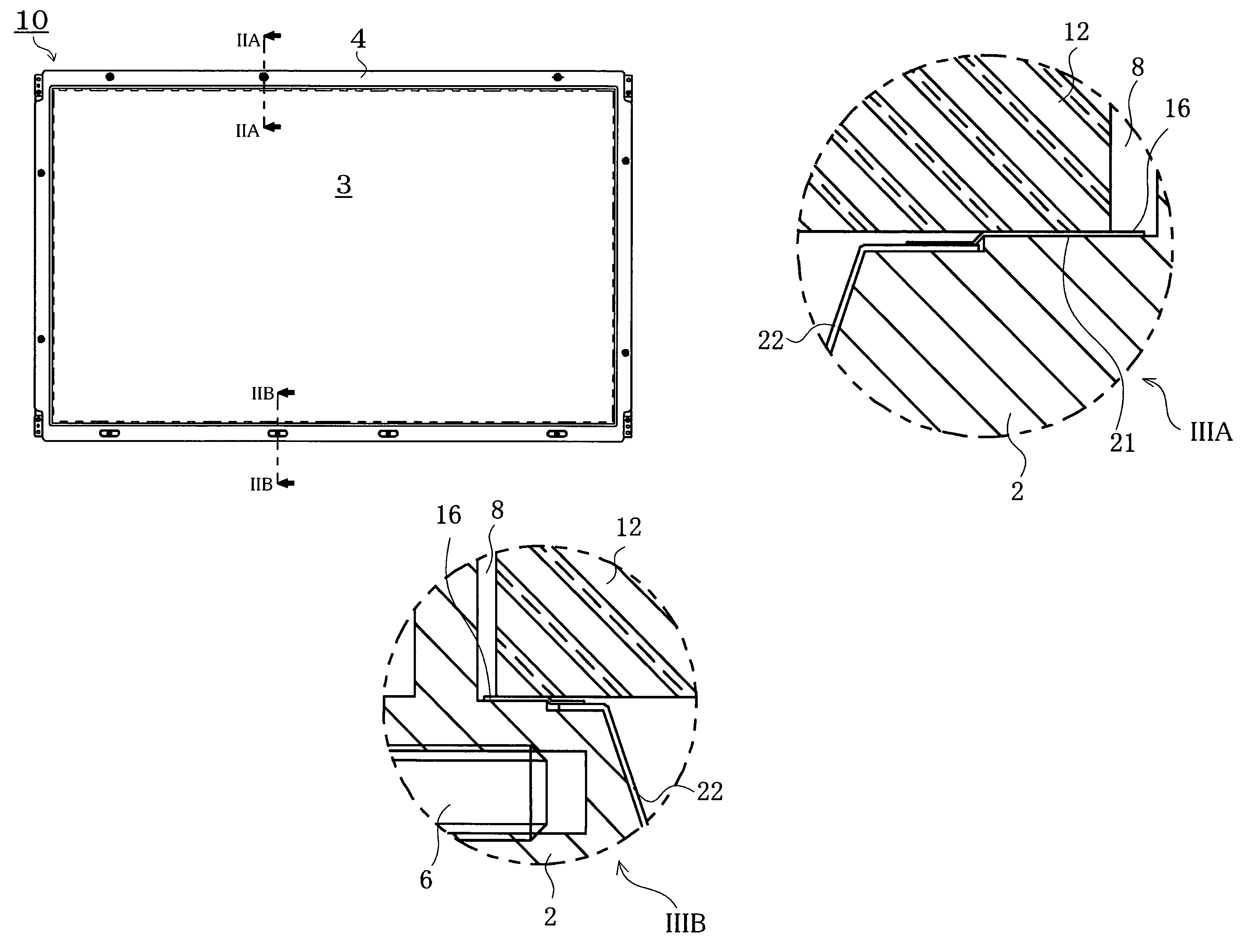
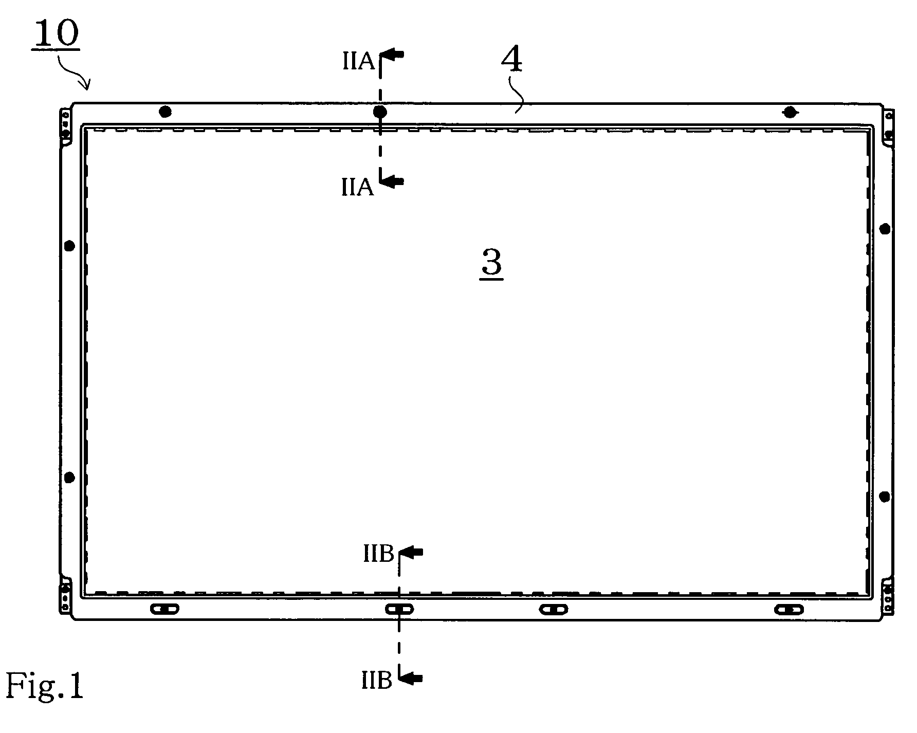
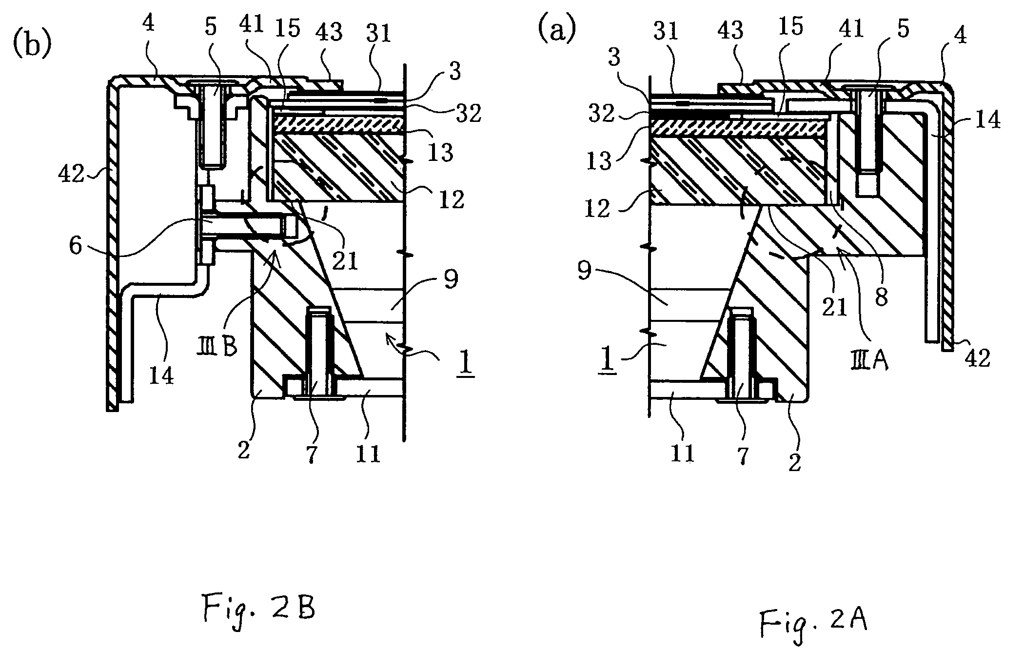
[0033]FIG. 1 is the plane view of the liquid crystal display device according to the first embodiment of the present invention. FIG. 2A is the enlarged sectional view at IIA-IIA of the liquid crystal display device referred to in FIG. 1, and FIG. 2B is the enlarged sectional view at IIB-IIB of the liquid crystal display device likewise referred to in FIG. 1. Further, FIG. 3A is the enlarged view of the area marked as IIIA in FIG. 2A, and FIG. 3B is the enlarged view of the area marked as IIIB in FIG. 2B. FIG. 4 is the perspective view showing another example of the friction reduction means in the first embodiment of the present invention, and FIG. 5 is the perspective view showing still another example of the friction reduction means in the first embodiment.

[0034]As shown in FIGS. 1 to 3, a liquid crystal display device 10 of the first embodiment consists of a liquid crystal panel 3, a bezel cover 4, and a direct type backlight unit 1, the rectangular and flat liquid crystal panel 3...

second embodiment

[0050]In the case of the large-sized liquid crystal display device, the central portion of the back surface reflector 11, the reinforcing plate 12, and the diffusion plate 13 are easily bent due to their own weight. To prevent this, protrusions referred to as spacer pins having a conical shape, for example, are often provided in the central portion or the like of the backlight unit 1 and used to support the optical sheet such as the reinforcing plate 12 and the diffusion plate 13, or in another case, reinforcing members are provided on the back surface reflector 11. Providing spacer pins is very effective in enabling the large-sized liquid crystal display device to carry out stable display. In addition, providing the reinforcing members on the back surface reflector 11 is also a very effective way of reducing the weight of the large-sized liquid crystal display device while maintaining its strength because a plate made of thin sheet metal can be used as the back surface reflector 11...


PUM

PropertyMeasurementUnit
sizeaaaaaaaaaa
diameteraaaaaaaaaa
diameteraaaaaaaaaa

Abstract

In a liquid crystal display device provided with a backlight unit, creak reduction means is provided at least on one part of the areas where members constituting the liquid crystal display device such as the liquid crystal panel, the diffusion plate, the reinforcing plate, the frame of the liquid crystal display device and the back surface reflector for the backlight unit come into contact with each other. The creak reduction means may be a slippery film whose surface is fluorinated such as a fluororesin film, a polyacetal resin film, a polyethylene film, and a silicon coating film, or protrusions or protruding fins, or a friction reduction means such as silicon oil or fluorine oil, or a mutual displacement absorbing means such as a flexible sheet.

Description

BACKGROUND OF THE INVENTION[0001]1. Field of the Invention[0002]The present invention relates to the management of noise in a large-sized liquid crystal display device, particularly to a liquid crystal display device in which the generation of noise due to friction occurring between members of the liquid crystal display device caused by thermal expansion after activation thereof, such as the liquid crystal panel, diffusion plate and reinforcing plate for a backlight unit, and frame, is prevented.[0003]2. Description of the Related Art[0004]Recently manufactured liquid crystal display devices have become larger in size, where the diagonal dimension of the screen generally ranges from 20 inches to 30 inches. Likewise, liquid crystal display devices with screens even exceeding a diagonal dimension of 40 inches have been developed and used to produce large-sized television sets, video display devices, or display devices of workstations and CAD devices. Such large-sized liquid crystal di...

Claims


Application Information

Patent Timeline
Patent Type & Authority Patents(United States)
IPC IPC(8): H05K5/00G02F1/1333G02F1/13G02F1/133G02F1/1335G02F1/13357G06F1/16
CPCG02F1/133308G02F2001/133317G02F1/133608G02F1/133604G02F1/133317G02F1/1333
Inventor NAKAGAWA, TAIJIMORIMOTO, SEIJIMITA, JUNYA
Owner SATURN LICENSING LLC
Learn More