Switching control circuit having a valley voltage detector to achieve soft switching for a resonant power converter

a technology of resonant power converters and control circuits, which is applied in the direction of dc-dc conversion, climate sustainability, power conversion systems, etc., can solve the problems of electric-magnetic interference (emi) and the generation of switching losses by the switching device, and achieve the effect of improving the efficiency of the power converter

Active Publication Date: 2008-09-16
SEMICON COMPONENTS IND LLC
View PDF12 Cites 52 Cited by
  • Summary
  • Abstract
  • Description
  • Claims
  • Application Information

AI Technical Summary

Benefits of technology

[0008]A switching control circuit having a valley voltage detector achieves the soft switching and improves the efficiency for a power converter. The switching control circuit includes a control circuit coupled to the feedback signal to generate a switching signal. Through an output circuit, the switching signal drives a switching device for switching a transformer and regulating the output of the power converter. The valley voltage detector is coupled to an auxiliary winding of the transformer for generating a control signal in response to the voltage of the transformer. The control signal is applied to enable the switching signal. The switching signal further turns on the switching device in response to a valley voltage across the switching device. The valley voltage detector comprises an input terminal connected to the auxiliary winding of the transformer through a resistor. The minimum voltage of the input terminal is regulated as a constant value, which makes a current flowed through the resistor is proportional to an inverse voltage of the transformer. A current mirror is coupled the input terminal to generate a voltage signal on a first resistor in response to the current flowed through the resistor. A waveform detector coupled to the input terminal produces a beginning signal in accordance with the transformer voltage. A phase lock circuit is coupled to the first resistor to generate the control signal in response to the peak value of the voltage signal and the beginning signal. Therefore, the control signal will enable the switching signal to soft switch the switching device.

Problems solved by technology

However, the switching of the switching device generates the switching losses and electric-magnetic-interference (EMI). FIG. 1 shows a flyback power converter and the waveforms are shown in FIG. 2.

Method used


Image

  • Switching control circuit having a valley voltage detector to achieve soft switching for a resonant power converter
  • Switching control circuit having a valley voltage detector to achieve soft switching for a resonant power converter
  • Switching control circuit having a valley voltage detector to achieve soft switching for a resonant power converter

Examples


Embodiment Construction

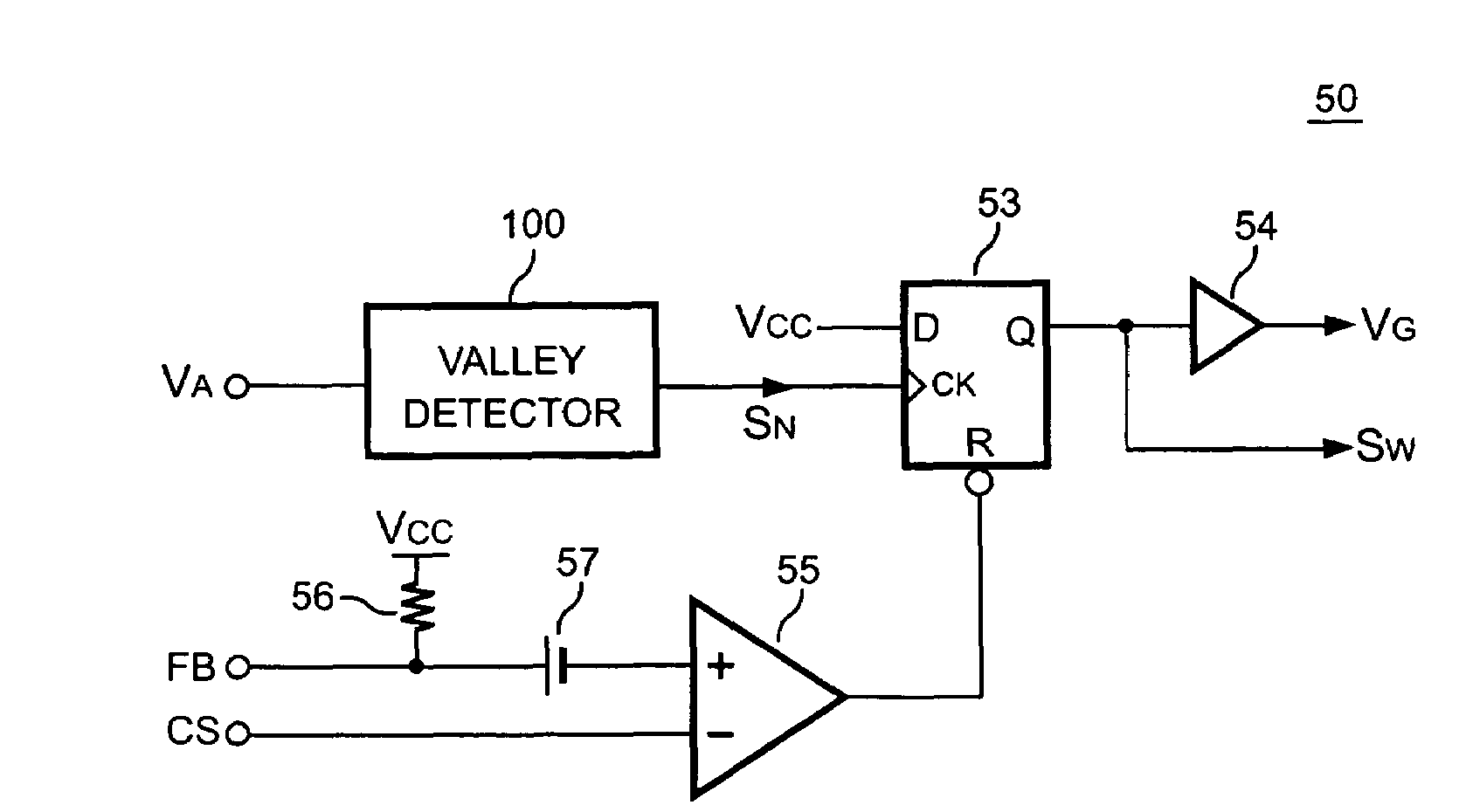
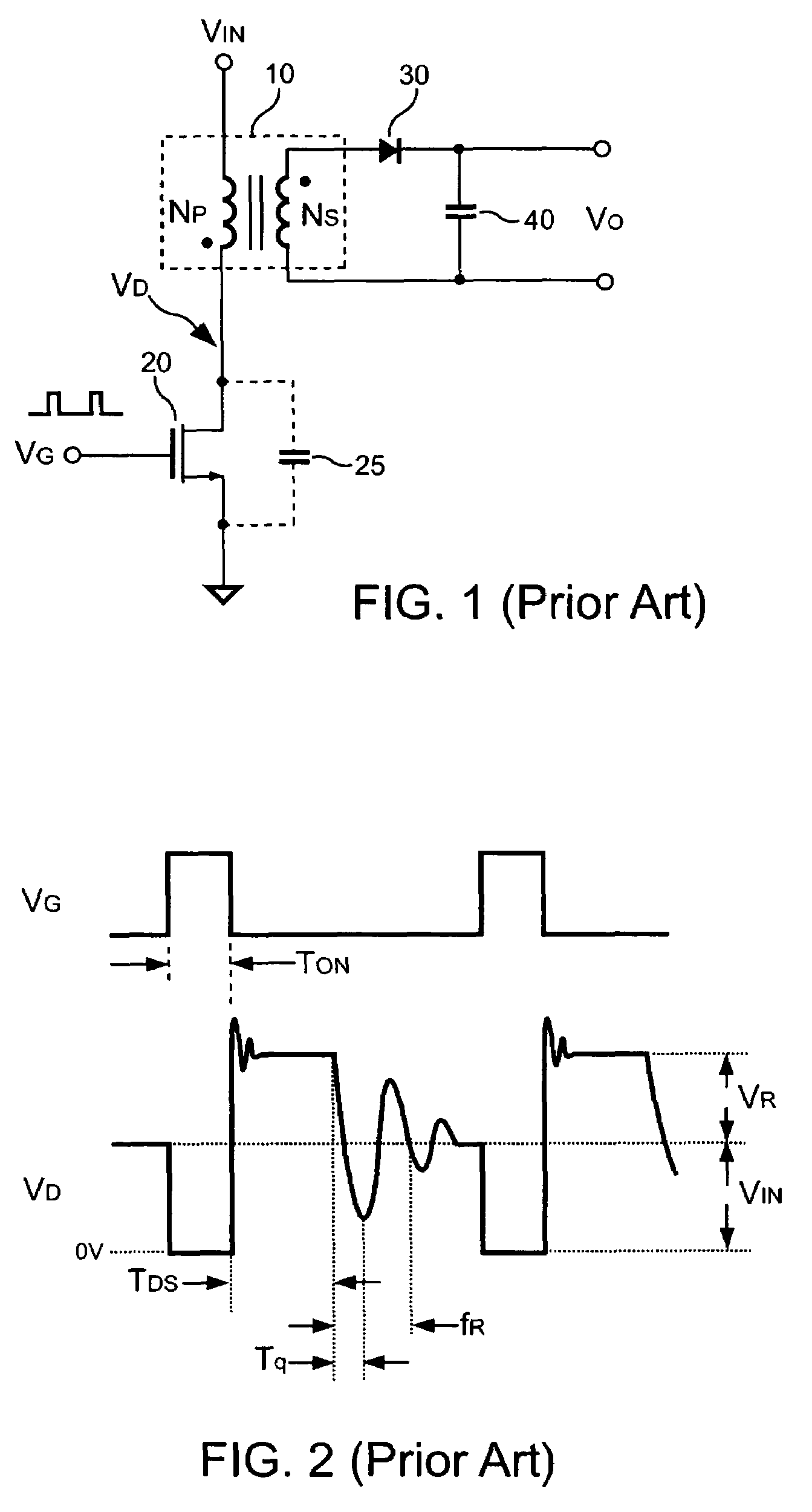
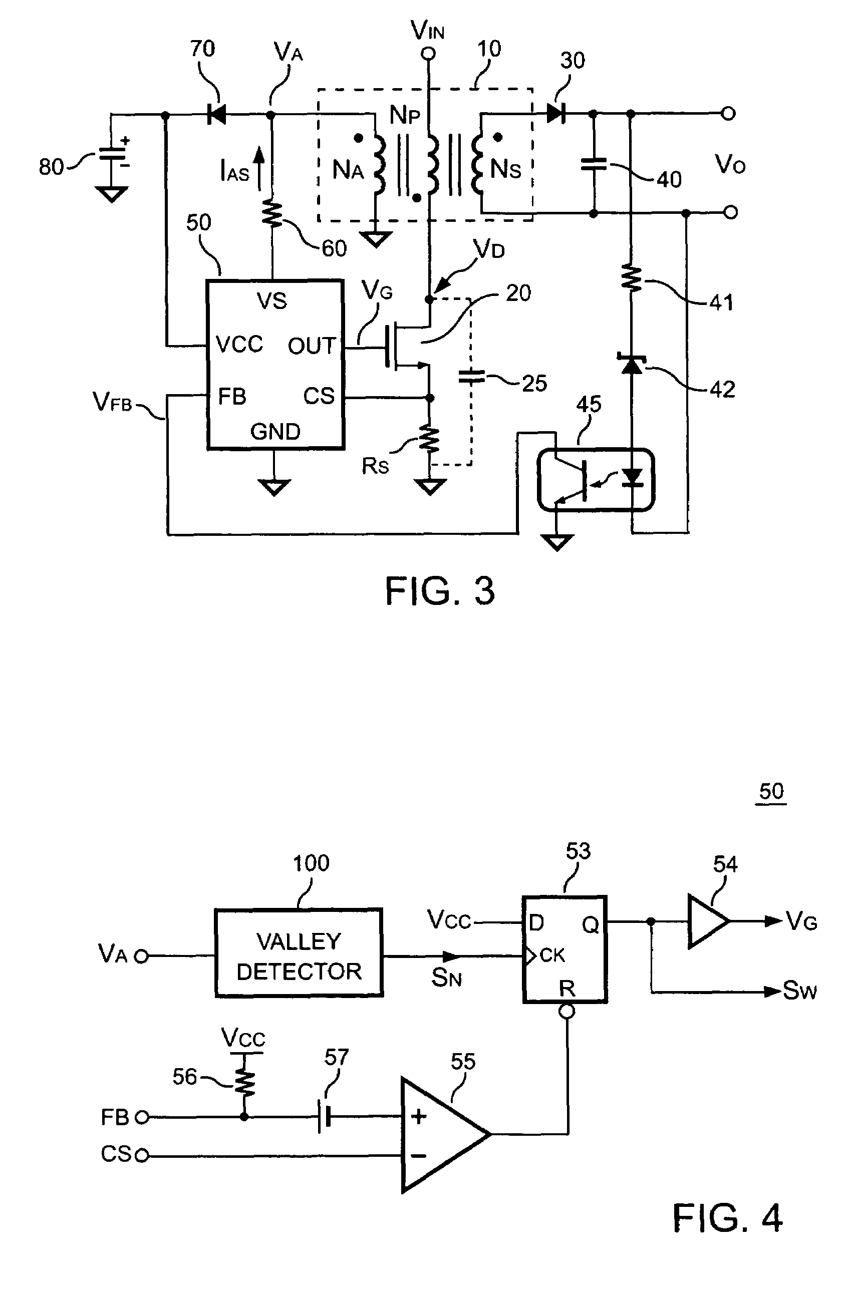
[0019]FIG. 3 is a preferred embodiment of a power converter, in which a switching control circuit 50 includes a feedback terminal FB, a current sense terminal CS, an input terminal VS and an output terminal. The output terminal generates an output signal VG to drive the switching device 20. The switching device 20 is further coupled to switch the transformer 10 (or a magnetic device) and generate a switching current signal on a current-sense resistor 25. The transformer 10 comprises a primary winding NP, a secondary winding NS and an auxiliary wind NA. The primary winding NP is connected to the switching device 20. The secondary winding NS is coupled to the output of the power converter through the rectifier 30 and the output capacitor 40. The auxiliary wind NA provides the power source for the switching control circuit 50 through another rectifier 70 and a capacitor 80. A resistor 60 is further connected from the auxiliary winding NA to the input terminal VS. An optical coupler 45 ...


PUM


Abstract

The present invention provides a switching control circuit having a valley voltage detector to achieve the soft switching and improve the efficiency of a power converter. The switching control circuit includes a control circuit coupled to the feedback signal to generate a switching signal. Through an output circuit, the switching signal drives a switching device for switching a transformer and regulating the output of the power converter. The valley voltage detector is coupled to an auxiliary winding of the transformer for generating a control signal in response to the voltage of the transformer. The control signal is used for enabling the switching signal. The switching signal further turns on the switching device in response to a valley voltage across the switching device.

Description

BACKGROUND OF THE INVENTION[0001]1. Field of Invention[0002]The present invention relates to a power converter, and more particularly, to a switching control circuit of the power converter.[0003]2. Description of Related Art[0004]Power converters are used to convert an unregulated power source to a regulated voltage or current source. The power converter normally includes a transformer or a magnetic device having primary winding and secondary winding to provide the isolation. A switching device connected in the primary winding to control energy transfer from the primary winding to the secondary winding. The power converter operates at a high frequency for allowing a size and weight reduction. However, the switching of the switching device generates the switching losses and electric-magnetic-interference (EMI). FIG. 1 shows a flyback power converter and the waveforms are shown in FIG. 2. The switching device 20 is applied to switch a transformer 10 and control the power delivered fro...

Claims


Application Information

Patent Timeline
Patent Type & Authority Patents(United States)
IPC IPC(8): H02M3/335
CPCH02M3/33523Y02B70/1433Y02B70/10
Inventor YANG, TA-YUNGLU, RUI-HONGLI, CHUH-CHINGTSAO, FENG-CHENGTSU, PEI-SHENG
Owner SEMICON COMPONENTS IND LLC
Why Eureka
Try Eureka