Communication within buildings

Inactive Publication Date: 2008-09-16
DORFMAN BERTRAND
View PDF11 Cites 27 Cited by
  • Summary
  • Abstract
  • Description
  • Claims
  • Application Information

AI Technical Summary

Benefits of technology

[0008]A further purpose of this invention is to provide inexpensive and reliable

Problems solved by technology

The construction of large buildings makes wireless communication within the buildings unreliable

Method used


Image

  • Communication within buildings
  • Communication within buildings
  • Communication within buildings

Examples


Embodiment Construction

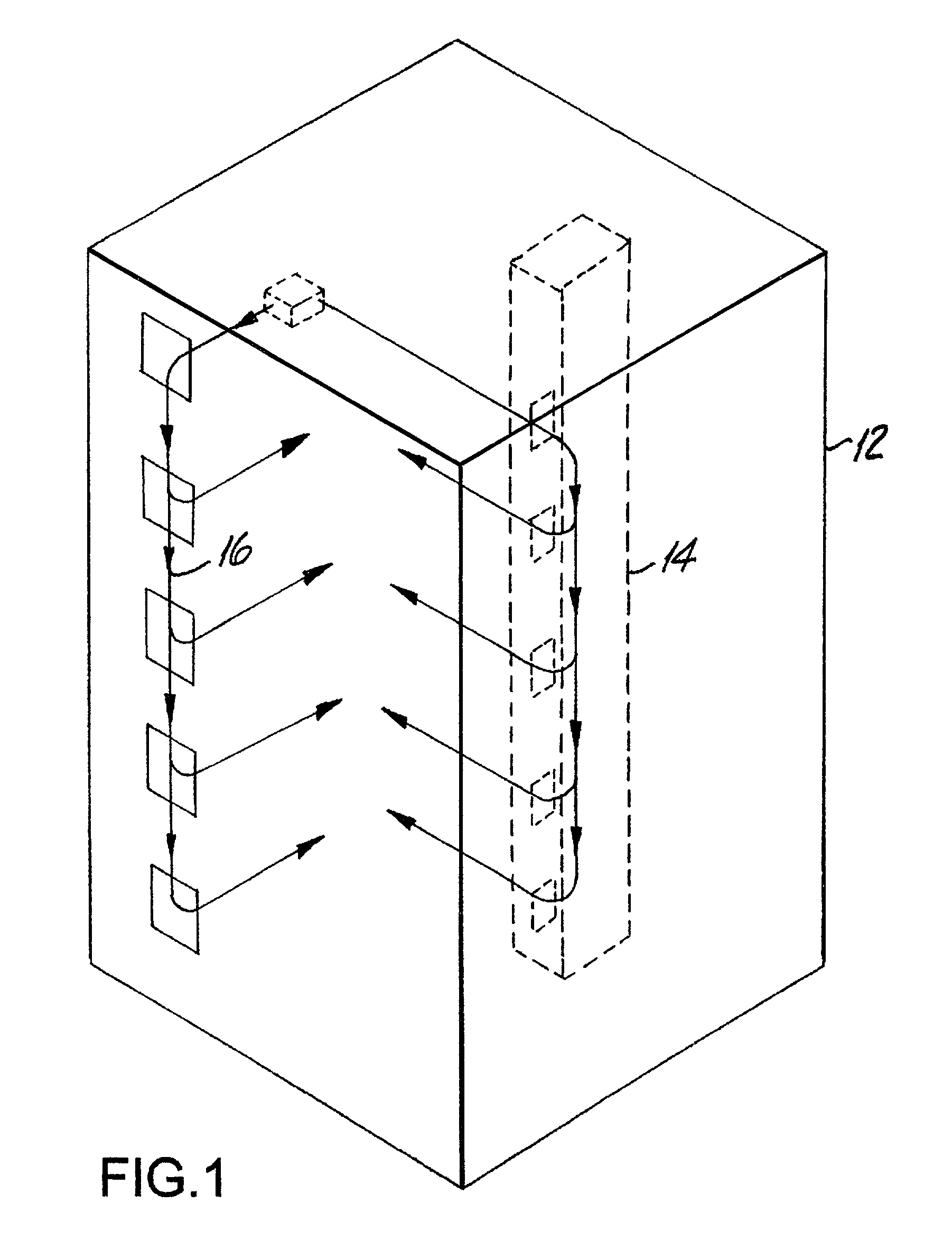
[0033]FIGS. 1 and 2 illustrate an embodiment of this invention applied to a large multi-story building. FIGS. 3 and 4 illustrate an embodiment of this invention applied to a single large floor of a building with convoluted passageways within that floor.

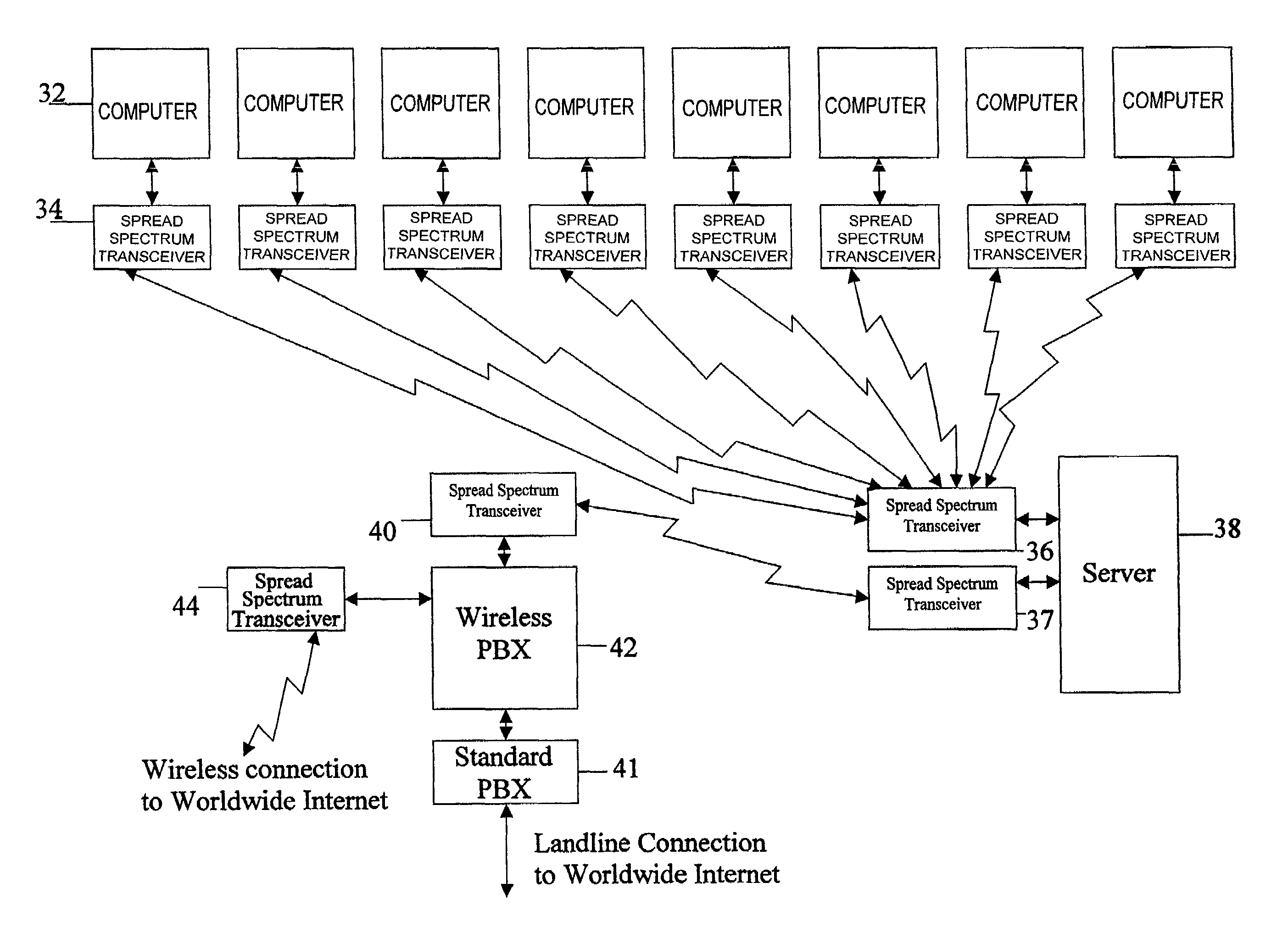
[0034]FIGS. 5 through 9 illustrate, in essentially block form, the equipment relationships involved in implementing the systems illustrated in FIGS. 1 through 4.

[0035]FIGS. 1 and 2 and 5 through 9 are the same as FIGS. 1 and 2 and 3 through 7 of the referenced patent application Ser. No. 09 / 596,516.

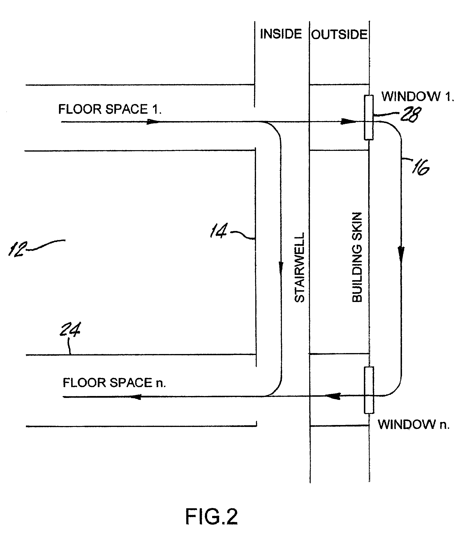
[0036]The FIG. 1 system is an arrangement in a large multi-story building 12 to provide signal transmission along selected paths. Specifically, stairwell shafts 14 and zones 16 located outside the building adjacent to the skin of the building are employed as transmission paths. These paths have been found to enable successful communication between virtually any two locations within the building.

[0037]As shown in FIG. 2, each floor 24 in a m...


PUM


Abstract

A system for communicating between stations which are at a number of different locations in a large building in which radio transmission is achieved through corridors or stairwell shafts or through windows along a zone outside of the building or any combination thereof. This system employs communication through spread spectrum transceivers and a set of directional antennas. At each station, one of the antennas is circular polarized and the other is linear polarized with a horizontal electrical component to facilitate reflection off the floors of the building. The spread spectrum is a hybrid frequency hopped and direct sequence modulated signal.

Description

REFERENCE TO RELATED APPLICATIONS[0001]This application is a continuation-in-part of application Ser. No. 09 / 596,516 filed Jun. 19, 2000 now U.S. Pat. No. 6,463,090 and entitled: Communication In High Rise Buildings.BACKGROUND OF THE INVENTION[0002]This invention relates to a communication system within a building and more particularly to communication along convoluted and non-linear paths in a building.[0003]A typical situation to which this invention is addressed is one where a number of people who occupy space in a large building operate computers and have a requirement to interact with each other and have access to each others' files and an Internet service provider on a real time basis. In order to satisfy this requirement, these computers must be interconnected in some manner and also connected with an Internet service provider. To accomplish this, a network is created which interconnects the computers through a central unit called a server, which acts as a library for files a...

Claims


Application Information

Patent Timeline
IPC IPC(8): H04B1/00
CPCH01Q21/24H01Q1/007
Inventor DORFMAN, BERTRAND
Owner DORFMAN BERTRAND
Why Eureka
Try Eureka