Controller for an electric vehicle and driving apparatus for the electric vehicle

a technology for electric vehicles and controllers, applied in the direction of electric devices, machines/engines, process and machine control, etc., can solve the problems of unstable power control, low voltage, and practically impossible to obtain the required torque, and achieve the effect of stable torque from the motor

Inactive Publication Date: 2008-09-23
HITACHI LTD
View PDF17 Cites 19 Cited by
  • Summary
  • Abstract
  • Description
  • Claims
  • Application Information

AI Technical Summary

Benefits of technology

[0007]The technology disclosed by JP-B-3396440 uses table data to change the motor current command in accordance with the battery voltage. Therefore, it makes it possible to exercise optimum, weak field control over each battery voltage and obtain stable torque from the motor.
[0011]It is an object of the present invention to provide a controller and driving apparatus for an electric vehicle, which enables a motor to steadily output torque even when there is an increase in the rotation speed of an internal combustion engine that drives a generator.
[0014]The above features make it possible to steadily output torque even when the engine speed increases in an electric vehicle that incorporates no battery and drives an AC motor by using only the power generated by a generator.

Problems solved by technology

Further, the power generation characteristic of the alternator indicates that there are a stable region where power control can be consistently exercised and an unstable region where power control is unstable.
This eventually leads to a situation where the voltage is extremely low.
Consequently, the above-mentioned voltage drop occurs, making it practically impossible to obtain required torque.
Even when the electric vehicle incorporates a battery, the above problem can occur if the output energy of the generator needs to be equal to the input energy of the inverter depending on the battery condition.

Method used


Image

  • Controller for an electric vehicle and driving apparatus for the electric vehicle
  • Controller for an electric vehicle and driving apparatus for the electric vehicle
  • Controller for an electric vehicle and driving apparatus for the electric vehicle

Examples


Embodiment Construction

[0029]The configuration and operation of a controller for an electric vehicle according to a first embodiment of the present invention will now be described with reference to FIGS. 1 to 13. For explanation purposes, the description of the first embodiment of the present invention relates to an electric four-wheel-drive vehicle whose rear wheels are driven by an AC motor.

[0030]First of all, the system configuration of an electric four-wheel-drive vehicle to which the controller according to the present embodiment is applied will be described.

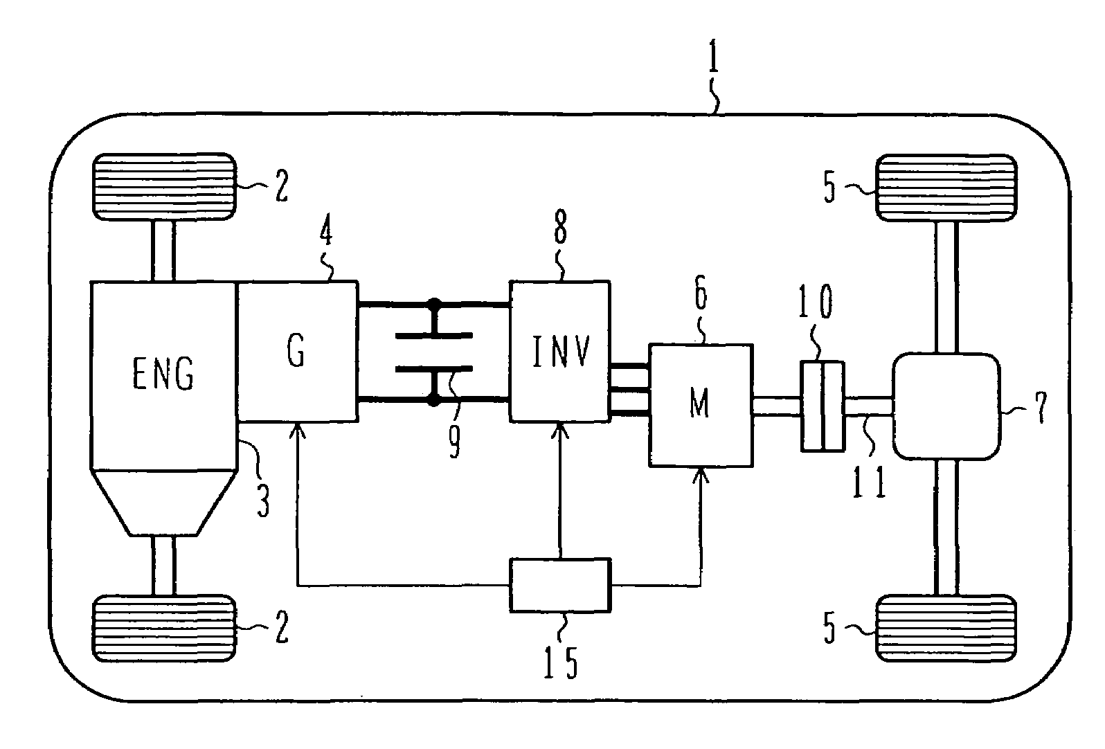
[0031]FIG. 1 is a system configuration diagram illustrating the electric four-wheel-drive vehicle to which the controller according to the first embodiment of the present invention is applied.

[0032]In the electric four-wheel-drive vehicle 1, a dedicated generator 4 is connected to an engine 3 that drives front wheels 2. An AC motor 6 generates motive energy on the basis of power generated by the generator 4. The generator 4 is an alternator whose...


PUM


Abstract

The present invention provides a controller and driving apparatus for an electric vehicle, which enables a motor to steadily output torque even when there is an increase in the rotation speed of an internal combustion engine that drives a generator. A motor control unit includes a voltage / current command generator F10. The voltage / current command generator F10 includes a base command determination unit, which determines a base command value for the output voltage of the generator and base command values for d- and q-axis currents that drive an AC motor, and power generation operating point change means, which changes the command values that are output from the base command determination unit. When an operating point of the generator approaches an unstable region where the generator unsteadily operates, the power generation operating point change means changes the generator's operating point to position it within a stable region.

Description

BACKGROUND OF THE INVENTION[0001]1. Field of the Invention[0002]The present invention relates to a controller for an electric vehicle and a driving apparatus for the electric vehicle, and more particularly to a controller and driving apparatus for an electric vehicle in which an internal combustion engine's rotational power drives a generator and the power generated by the generator drives a motor.[0003]2. Description of the Related Art[0004]In recent years, an increasing number of electric vehicles are running by using a motor as a driving source. They are electric automobiles, hybrid automobiles, and other environment-responsive automobiles. These environment-responsive automobiles are mainly characterized by the fact that they carry a battery, use the power stored in the battery to let the motor generate torque, and drive tires for running purposes. Recently, a permanent-magnet synchronous motor or other AC motor is employed as the motor for downsizing purposes (for achieving a h...

Claims


Application Information

Patent Timeline
Patent Type & Authority Patents(United States)
IPC IPC(8): H02P27/04G06G7/70B60L50/10B60K6/44B60K6/52B60L50/13B60L50/16B60W10/08B60W20/00F02D29/02F02D29/06
CPCB60K6/44B60K6/52B60L11/02B60L11/08B60L11/123B60L11/14B60L15/025B60W10/08H02P9/14B60K6/46Y02T10/7077B60L2220/14B60L2220/18B60L2240/441B60L2260/28B60W20/00B60W2510/0638Y02T10/6217Y02T10/623Y02T10/6265Y02T10/643Y02T10/7022B60L50/10B60L50/13B60L50/61B60L50/16Y02T10/62Y02T10/64Y02T10/70Y02T10/7072B60W20/10B60W2710/086H02P27/04B60W10/06
Inventor KANEKO, SATORUYAMAMOTO, TATSUYUKIKATSUHAMA, KENTAAKAISHI, SHIGERUIINO, HISAO
Owner HITACHI LTD
Why Eureka
Try Eureka