
High performance capacitor with high dielectric constant material

a dielectric constant, capacitor technology, applied in the direction of wound capacitors, fixed capacitor details, fixed capacitors, etc., can solve the problems of limited ability to dramatically improve the output and cycle life of batteries, rarely exceeding 200 whr/kg of batteries, etc., to achieve high performance and high energy-density capacitors.

Inactive Publication Date: 2008-09-23
DOWGIALLO JR EDWARD J
View PDF29 Cites 55 Cited by
  • Summary
  • Abstract
  • Description
  • Claims
  • Application Information

AI Technical Summary

Benefits of technology

[0008]The present invention overcomes the obstacles and limitations described above by providing a high performance and high energy-density capacitor with power characteristics exceeding known capacitors.
[0009]The present invention also provides high performance and high energy-density capacitors utilizing a nanostructure to provide a nanocapacitor with specific energies ranging from 10 Whr / kg to more than 10,000 Whr / kg with corresponding energy densities.
[0010]Another object of the present invention is to provide an extremely high energy nanocapacitor by significantly increasing the dielectric constant of the device and the corresponding structure and configuration. The present invention makes use of high permittivity materials within the nanostructure of the capacitors to obtain power characteristics not previously realized in capacitors.
[0011]Prior to the present invention, the use of high permittivity materials has focused on their application within conventional PCB (Printed Circuit Board) sized components. The technology push prior to the present invention has been towards small real-estate devices such as surface mount components, in-circuit components, or embedded circuit board components in an effort to reduce overall circuit board size while maintaining power characteristics. The present invention provides a nanocapacitor device, structure and fabrication method which enables high permittivity dielectrics to be utilized in scalable capacitors to exceed the power characteristics of known capacitors.
[0016]Stull further, the capacitor of the present invention may be positioned and connected to additional capacitors to form an array, bank, or grid. The array, bank, or grid could employ fuses to prevent the entire array, bank, or grid from shorting if one capacitor is shorted.

Problems solved by technology

However, batteries rarely exceed 200 Whr / kg and their cycle life rarely exceeds 1,000 cycles.
Further, there appears to be limited ability to dramatically improve the output and cycle life of batteries from a chemistry standpoint.
However, fuel cells have several limitations including high manufacturing costs, complexity, size and weight.
However, conventional and known capacitors have power limitations, including double layer or ultra-capacitors, with these capacitors not exceeding 15 Whr / kg.

Method used


Image

  • High performance capacitor with high dielectric constant material
  • High performance capacitor with high dielectric constant material
  • High performance capacitor with high dielectric constant material

Examples


Embodiment Construction

[0029]The system of the present invention will now be described in conjunction with FIGS. 1-11. The present invention provides a capacitor which overcomes the limitations described above by providing high performance and high energy-density nanocapacitor.

[0030]Nanostructure multilayer materials are characterized by their near-atomic scales (particle size and layer thickness) and large ratios of interfacial area to volume. Through deposition processes it is now possible to produce thick macroscopic nano-structure multilayer materials to fabricate free standing high quality structures above 300 microns thick and containing up to 50,000 individual layers. The present invention provides a parallel-plate conductor-dielectric structure capacitor designed and fabricated using multilayer technology with engineered properties affected by structure or design, materials selection, the synthesis process, and materials processing. The flexibility in materials and processes provide a great advant...


PUM

PropertyMeasurementUnit
dielectric constantaaaaaaaaaa
thickaaaaaaaaaa
thicknessaaaaaaaaaa

Abstract

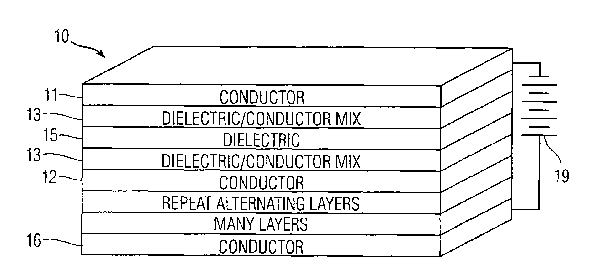
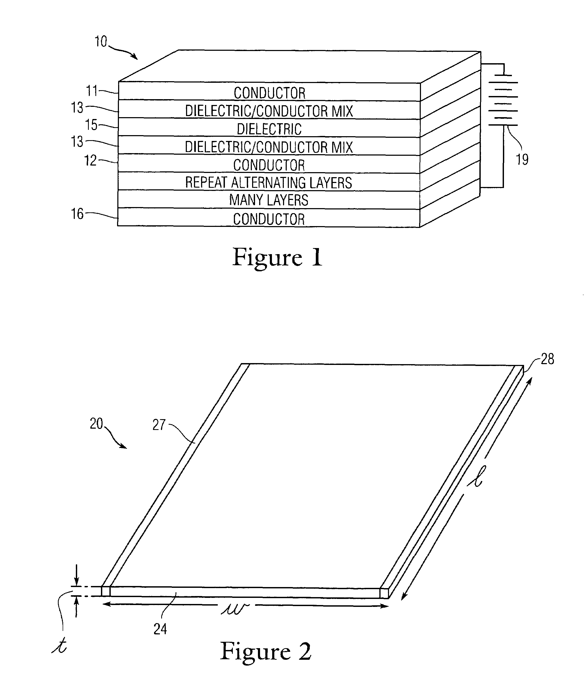
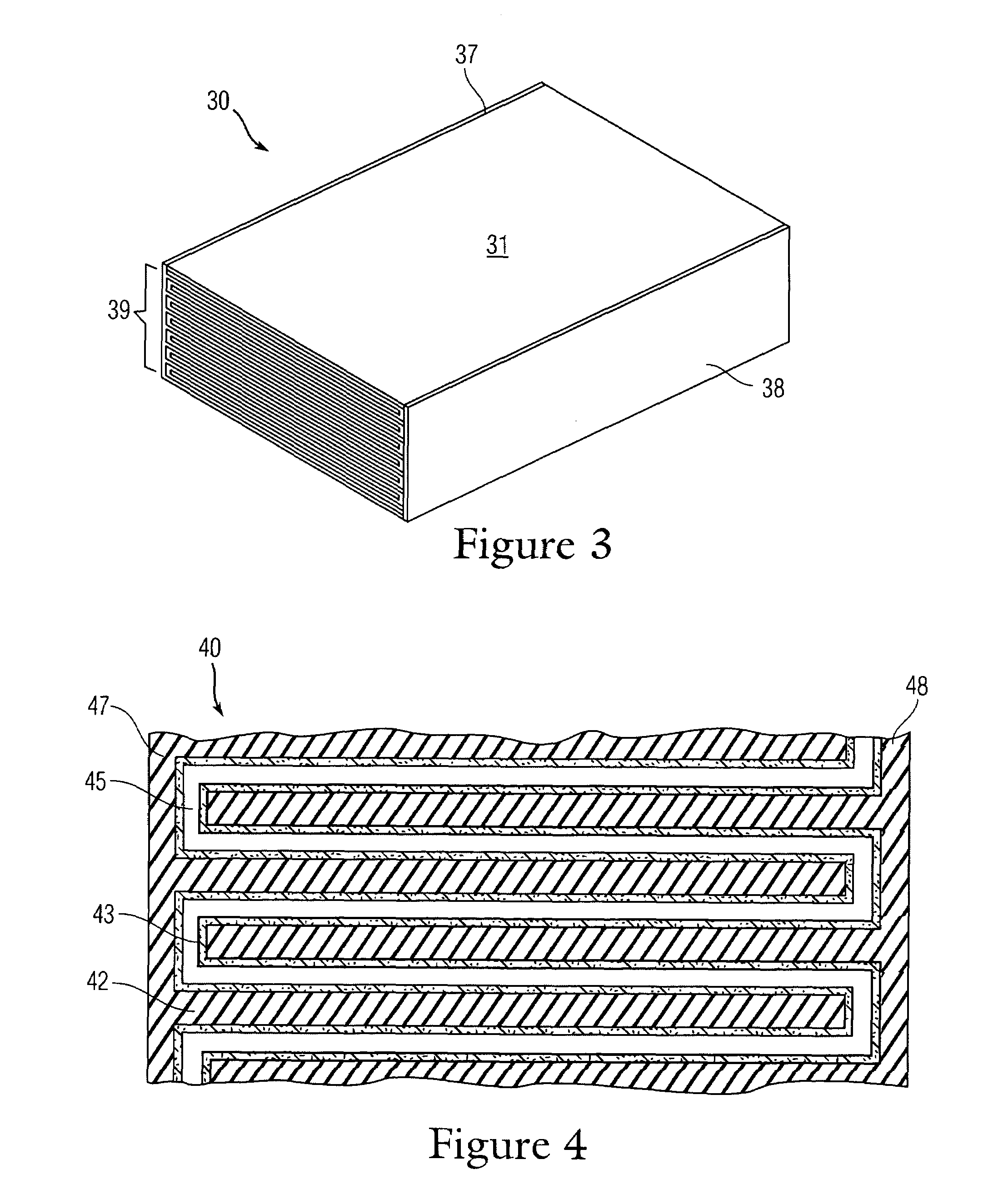
A multilayered high performance capacitor formed of two or more conductors with a dielectric layer and one or more a dielectric-conductor interface layer sandwiched in between the conductors. The capacitor may be fabricated using many thin layers, at the nano level, providing a nanocapacitor. The capacitor may employ an interleaved structured where numerous conductor layers are interleaved with other conductor layers. The dielectric layers may be multilayered or a single layer and may consist of materials with high dielectric constants ranging from 800 to over 1 million, including materials in the perovskite-oxide family. The capacitor can be shaped, sized and the appropriate materials selected to obtain breakdown voltages within the range of 0.1 to over 11 MV / cm and to obtain specific energies and energy densities equivalent to or exceeding the power characteristics of known capacitors, fuel cells, and batteries. The nanocapacitor may be combined with other nanocapacitors to form stacks, packs, or grids of cells where the cells may be connected in series, parallel or both to provide increased energy or power characteristics.

Description

[0001]This application claims the benefit of U.S. Provisional Patent Application 60 / 633,117 filed on Dec. 3, 2004, the entirety of which is incorporated herein by reference.FIELD OF THE INVENTION[0002]The present invention relates generally to the field of capacitors. Particularly, the present invention relates to high performance and high energy-density capacitors, their related structure and method of fabrication.BACKGROUND OF THE INVENTION[0003]Capacitors are one of the earliest electrical components and essentially consist of two parallel plates which possess a certain capacity to store an electric charge separated by a dielectric material. The effectiveness of a given capacitor is determined by the structure of the capacitor, the plates, the dielectric material, and the method of fabrication.[0004]Capacitors provide a reliable source of power in many applications. Although they are widely used on integrated circuits (ICs) they are also used as a power supply source for non-IC a...

Claims


Application Information

Patent Timeline
Patent Type & Authority Patents(United States)
IPC IPC(8): H01G4/06
CPCH01G4/12H01G4/1218H01G4/30H01G4/248Y02T10/7022Y02T10/70
Inventor DOWGIALLO, JR., EDWARD J.
Owner DOWGIALLO JR EDWARD J
Learn More