Method and apparatus for reduction of optical coupling between pump lasers and photodetectors in optical amplifiers

a technology of optical amplifier and pump laser, which is applied in the field of optical amplifier, can solve the problems of unguided power, leakage of pump laser light, unwanted light transfer between components, etc., and achieve the effect of preventing the entry of ambient pump laser

Active Publication Date: 2008-09-30
II VI DELAWARE INC
View PDF3 Cites 19 Cited by
  • Summary
  • Abstract
  • Description
  • Claims
  • Application Information

AI Technical Summary

Benefits of technology

[0017]A second preferred embodiment of a fiber amplifier apparatus in accordance with the present invention comprises an optical gain medium having a first end and a second end; an input fiber optically coupled to and delivering an optical signal to the first end; an output fiber optically coupled to and receiving an amplified optical signal from the second end; at least one pump light fiber optically coupled to the optical gain medium and delivering pump laser light to the optical gain medium; at least one monitor fiber optically coupled to one of the input fiber and the output fiber; at least one photodetector optically coupled to at least one monitor fiber; and at least one optical filter optically coupled between a monitor fiber and a photodetector. An optical filter within the second preferred embodiment of a fiber amplifier transmits signal light to the photodetector and prevents transmission of pump laser light to the photodetector. Such a filter may either be a bandpass filter or a long-wave pass filter.
[0019]The light-absorbing coating applied to the cladding of either or both of the at least one pump light fiber and the at least one monitor fiber serves to reduce coupled light in at least one of three possible ways: (1) attenuation of light leaving the pump light fiber or propagating within the cladding or coating of the pump light fiber; (2) prevention of the entry of ambient pump laser into the monitor fiber; and / or (3) attenuation of unwanted light propagating in the monitor fiber.

Problems solved by technology

The close proximity of components within the conventional optical amplifier configuration (FIGS. 1-2) presents some problems in terms of unwanted light transfer between components.
Some of this power is not in a truly guided mode and the cladding and coating are acting more like a lossy “light pipe”.
The leakage of pump laser light illustrated in FIG. 3 presents a difficulty and potential disadvantage regardless of whether the fiber 12 is coated or uncoated.
The resulting duplication of components and fibers (relative to those shown in FIG. 1) and the provision of additional components as well as the splices or couplers between such components causes even more opportunities for light cross contamination within the housing configuration shown in FIG. 2.
The use of a cover or coating on the fiber (so as to prevent the coupling) disadvantageously requires that very long sections of fiber be so covered or coated in order to assure that no coupling takes place within any section of any of the various fibers.
Most of such covering or coating will be unnecessary since potential inter-fiber coupling only occurs at certain locations.
Further, if any inter-fiber optical coupling should occur at some point because of, for instance, a break in the covering or coating, then the remaining covering or coating will be rendered useless since it cannot remove the contamination light once it has entered a fiber.
Finally mechanical separation of fibers adds significant additional bulk to the overall apparatus.

Method used


Image

  • Method and apparatus for reduction of optical coupling between pump lasers and photodetectors in optical amplifiers
  • Method and apparatus for reduction of optical coupling between pump lasers and photodetectors in optical amplifiers
  • Method and apparatus for reduction of optical coupling between pump lasers and photodetectors in optical amplifiers

Examples


Embodiment Construction

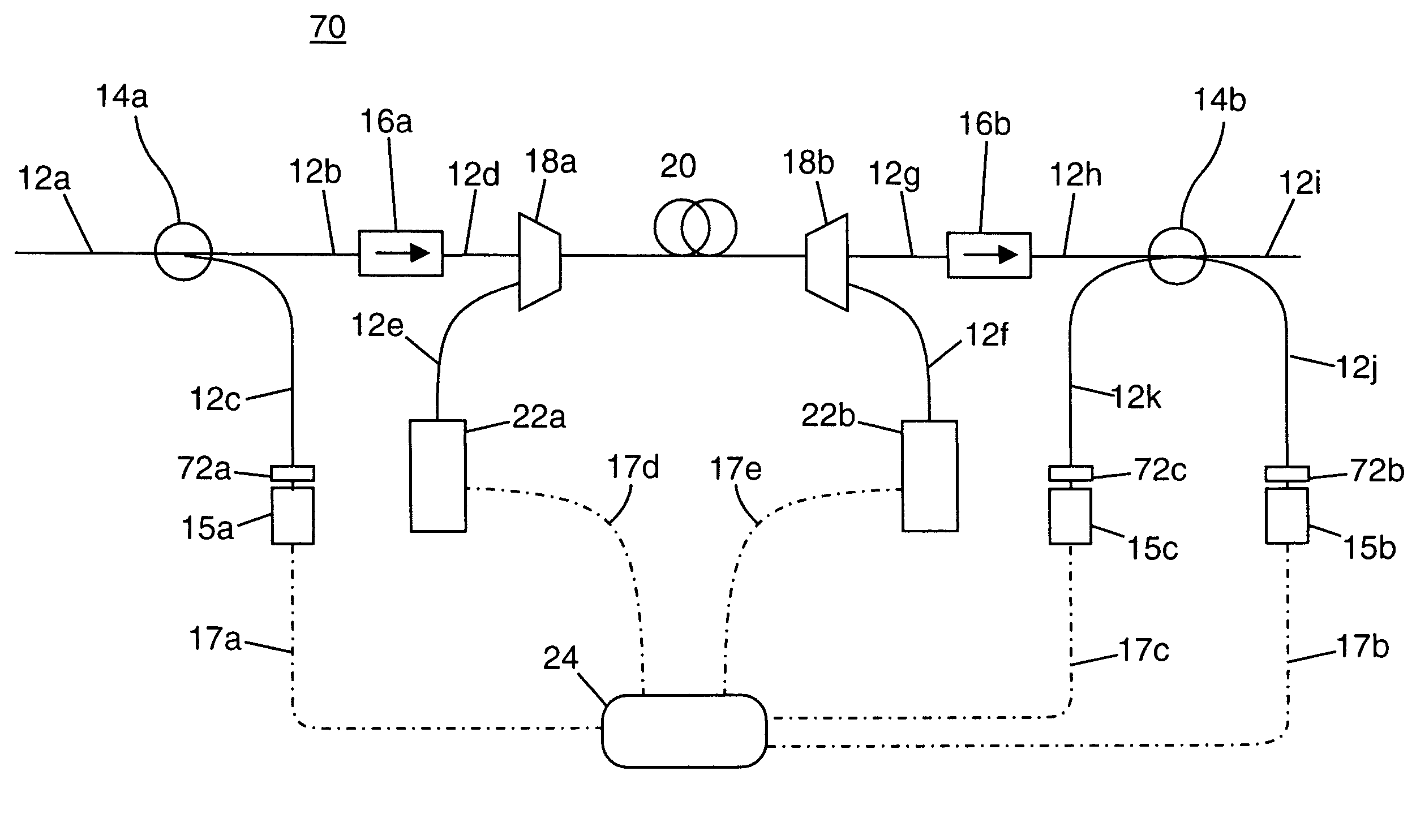
[0028]The present invention relates to an improved method and apparatus for reduction of optical coupling between pump lasers and photodetectors in optical amplifiers. The following description is presented to enable one of ordinary skill in the art to make and use the invention and is provided in the context of a patent application and its requirements. Various modifications to the preferred embodiment will be readily apparent to those skilled in the art and the generic principles herein may be applied to other embodiments. Thus, the present invention is not intended to be limited to the embodiment shown but is to be accorded the widest scope consistent with the principles and features described herein. To more particularly appreciate the features and advantages of the present invention, the reader is referred to the appended FIGS. 4-7 in conjunction with the following discussion.

[0029]FIG. 4 is a drawing of a first preferred embodiment of an optical filter apparatus in accordance ...


PUM


Abstract

In a first aspect, the present invention comprises an optical filter comprising a fiber having a core and a cladding and a light-absorbing coating applied onto a portion of the fiber cladding, the coating attenuating loosely bound cladding modes. In another aspect, the invention comprises a fiber amplifier apparatus comprising fibers for delivering pump laser light and for monitoring signal light and at least one photodetector optically coupled to a monitoring fiber, wherein either an optical filter is disposed between a monitoring fiber and a photodetector or at least one of the fibers has a core and a cladding and a light-absorbing coating applied onto a portion of the fiber cladding. A method in accordance with the present invention includes providing an optical amplifier having fibers for delivering pump laser light and for monitoring signal light, and applying a light-absorbing coating onto a portion of one of said fibers.

Description

FIELD OF THE INVENTION[0001]The present invention relates to optical amplifiers used to boost optical power of light signals within optical transmission systems. More particularly, the present invention relates to optical amplifiers having improved performance of monitor photodetectors through reduced inter-fiber coupling of pump laser light into the monitor photodetectors.BACKGROUND OF THE INVENTION[0002]Optical amplifiers are important components of fiber-optic communication systems. Erbium-doped fiber amplifier (EDFA) systems have become especially popular owing to their gain characteristics near the 1.5 μm transmission band of conventional optical fiber. An example of a typical conventional EDFA 10 is shown in FIG. 1. It is to be kept in mind that FIG. 1 is provided for example only and that, since EDFA designs are varied, not every component shown in FIG. 1 may be included in a particular EDFA design. Alternatively, more-complex EDFA designs may include additional components no...

Claims


Application Information

Patent Timeline
Patent Type & Authority Patents(United States)
IPC IPC(8): G02B6/02
CPCG02B6/02G02B6/4215G02B6/29367G02B6/02052
Inventor WILLIAMS, MARTIN R.
Owner II VI DELAWARE INC
Why Eureka
Try Eureka