Cooler head vaporizer

a technology of vaporizer and cooling head, which is applied in the direction of steam generation using steam absorption, lighting and heating apparatus, heating types, etc., can solve the problems of water droplets being sprayed, and achieve the effect of reducing the temperature of water vapor

Active Publication Date: 2008-09-30
HELEN OF TROY LIMITED
View PDF10 Cites 0 Cited by
  • Summary
  • Abstract
  • Description
  • Claims
  • Application Information

AI Technical Summary

Benefits of technology

[0009]Additionally, the steam generating unit cover portion includes a water vapor outlet for directing water vapor created in the inner or boiling chamber and a condensation recycling port that serves to return the water droplets that form about the steam generating unit cover portion. Situated above the steam generating unit cover portion is a safety grill. The safety grill includes openings or vents that allow the water vapor to be directed by the water vapor outlet into the environment. The safety grill establishes a particular distance between the water vapor outlet and the point at which the steam is contactable by an individual in the open environment. The vents of the safety grill also allow ambient air to mix with the water vapor to reduce the temperature of the water vapor exiting through the safety grill. As a result, the temperature of the water vapor exiting through the safety cage is reduced to the cooler temperature of about 160-180 degrees Fahrenheit.
[0010]Along the top side of the steam generating unit top cover portion is a water barrier. The water barrier, a raised wall-like structure, is situated generally about the center axis of the steam generating unit top cover portion. The water barrier separates the electrical connectors and components from the water vapor outlet. As noted, condensation may form in the vicinity of the water vapor outlet. The water barrier serves to protect the electrical components of the vaporizer from malfunction due to exposure to the water droplets resulting from condensation or spraying.

Problems solved by technology

As the boiling chamber produces the water vapor, it may occasionally cause spraying of water droplets.

Method used


Image

  • Cooler head vaporizer
  • Cooler head vaporizer
  • Cooler head vaporizer

Examples


Embodiment Construction

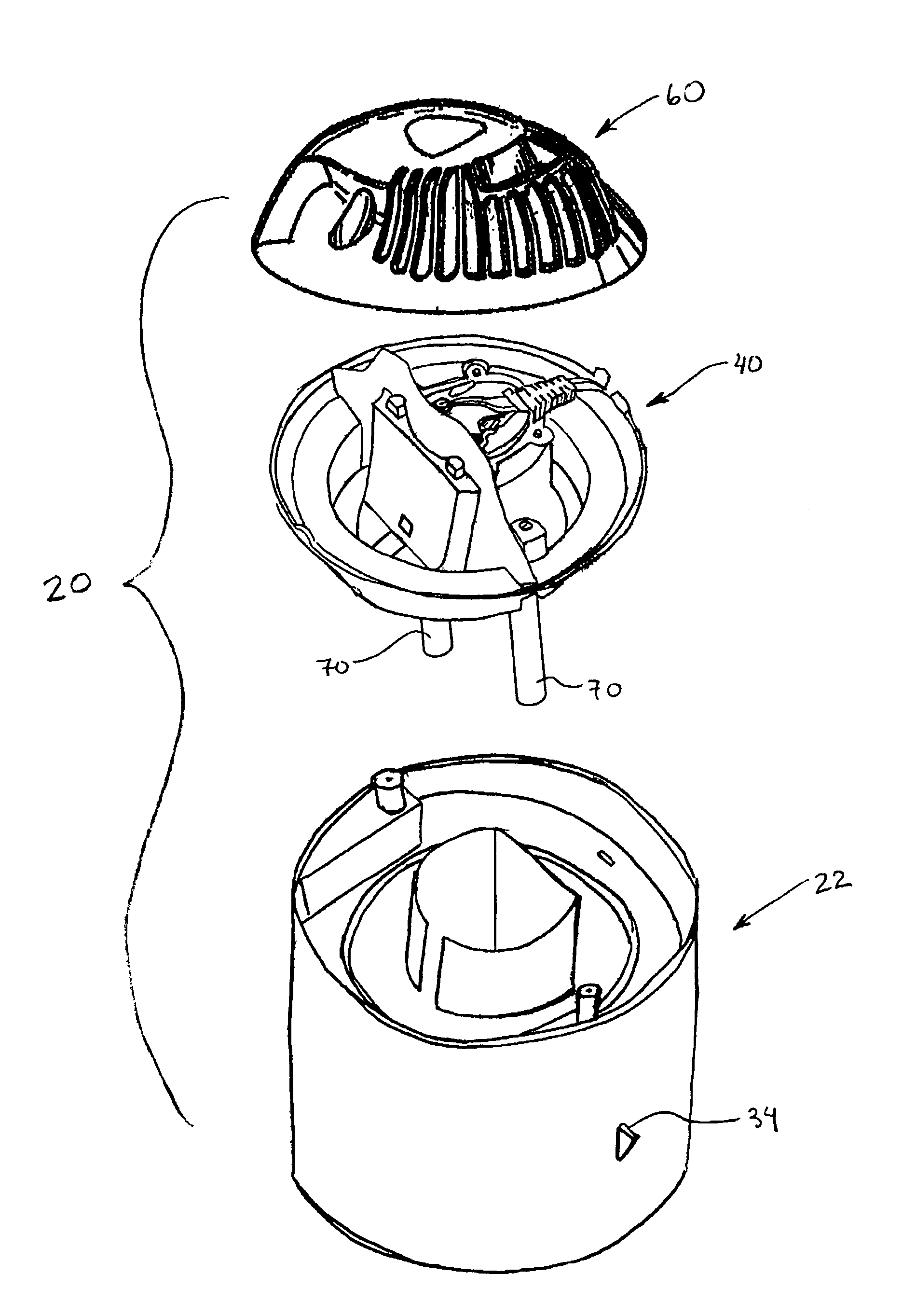
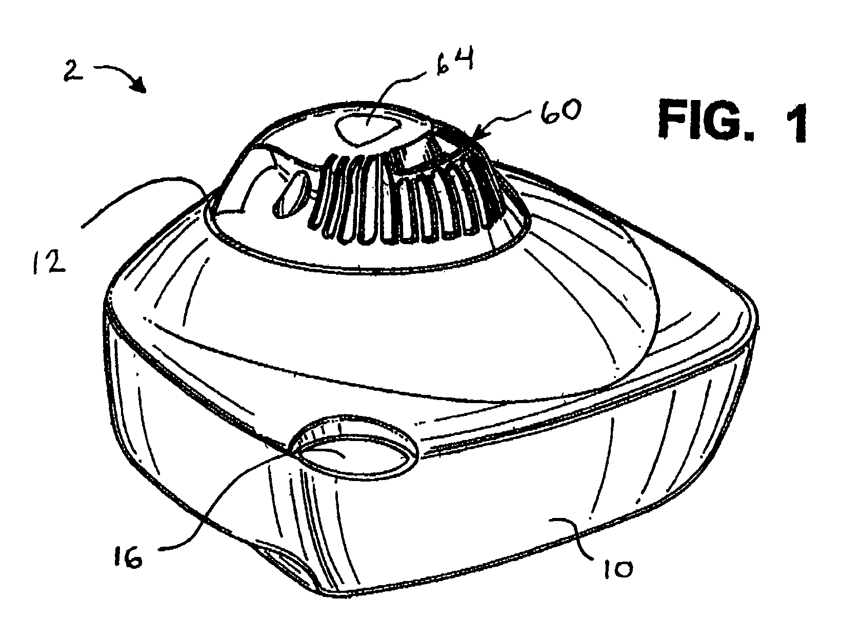
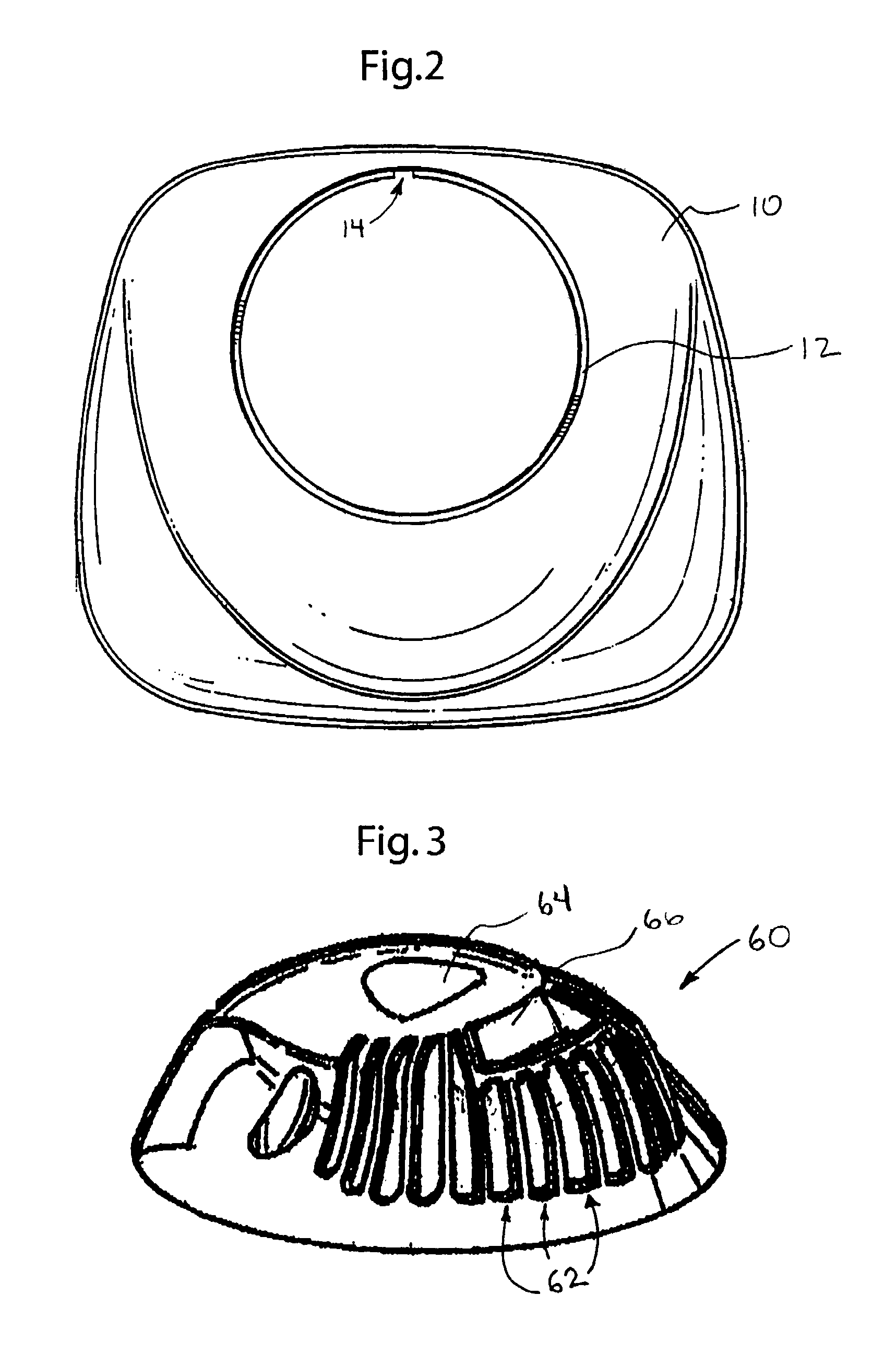
[0020]Referring now to FIGS. 1-7, the present invention is directed to a vaporizer 2 that emits water vapor through an outlet into the environment while maintaining a reduced temperature of that vapor at an outlet. As the temperature of the vapor has been reduced, condensation droplets form more rapidly than with typical vaporizers. The vaporizer of the present invention recycles the water droplets by directing them back into a boiling chamber 24. Alternately, the water droplets are directed into an outer water chamber 28 before being directed back into boiling chamber 24 (FIG. 7).

[0021]Referring now to FIGS. 1 and 4-7, the vaporizer of the present invention includes a water tank 10 having an opening 12 on its top surface for receiving a steam generating unit 20. As can be seen in FIG. 4, the steam generating unit 20 is an assembly that includes a triple-walled chamber 22, a steam generating unit cover portion 40 and a safety grill 60. As illustrated in FIG. 1, the steam generating ...


PUM

PropertyMeasurementUnit
temperatureaaaaaaaaaa

Abstract

A vaporizer for providing water vapor at a safer and reduced temperature comprises a water tank and steam generating unit. The steam generating unit is an assembly of a multi-walled chamber, top cover portion and safety grill. The safety grill establishes a distance between a water vapor outlet situated on the top cover portion and the point where an individual may contact the water vapor. This distance allows the temperature of the water vapor to be reduced to a safer temperature. Additionally, the vaporizer includes a condensation recycling port that receives water vapor droplets that form about the steam generating unit and returns those droplets to a boiling chamber where the water droplets are recycled into water vapor. Finally, the top cover portion includes a water barrier to protect electrical components near the water vapor outlet.

Description

FIELD OF THE INVENTION[0001]The present invention generally relates to the field of vaporizers and humidifiers, and more specifically to a vaporizer enabled to provide a cooler and, therefore, safer stream of vapor to the environment.BACKGROUND OF THE INVENTION[0002]Various types of products for increasing the humidification levels of an environment have been in common use for many years. Environments having low levels of humidity, such as the home or office, result in an overall discomfort to the individuals in that environment, particularly during the winter season. Typical problems resulting from low humidity levels in the home are dry sinus cavity and nasal passages, dry and itchy skin that can result in the development of rashes, and scratchy throats. Additionally, maintaining reasonable levels of humidification is especially important for those with respiratory ailments, particularly young children. An environment having an adequate level of humidification improves recovery ti...

Claims


Application Information

Patent Timeline
Patent Type & Authority Patents(United States)
IPC IPC(8): H05B3/60F22B1/20
CPCF24F6/18F22B1/30
Inventor HOWANSKY, ANDREWWANG, ZHIJINGHOTZ, LINDAKANEL, CHRISTOPHER S.
Owner HELEN OF TROY LIMITED
Why Eureka
Try Eureka