Fluid circuit heat transfer device for plural heat sources

a heat transfer device and flue circuit technology, applied in the direction of insulated conductors, cables, separation processes, etc., can solve the problems of reducing efficiency, increasing capacity generally also increasing size or expense, and reducing the rate of thermal transfer to the ambient, so as to achieve the effect of discharging hea

Active Publication Date: 2008-10-07
THERMAL
View PDF17 Cites 59 Cited by
  • Summary
  • Abstract
  • Description
  • Claims
  • Application Information

AI Technical Summary

Benefits of technology

[0014]It is an object of the present invention to provide a practical arrangement for dissipating heat from two or more distinct heat sources that potentially produce different levels of heat energy, such as two integrated circuit packages on a printed circuit board.

Problems solved by technology

For example, increases in capacity generally also increase size or expense.
Having a lower temperature gradient reduces the rate of thermal transfer to the ambient, i.e., reduces efficiency.
There is a challenge in the case of modern integrated circuit devices such as computer desktop and lap top devices, consumer electronics and similar equipment.
It is difficult to provide a heat sink heat pipe optimized for each heat source due to the range of different devices and the different operational and ambient conditions that may arise.
Moreover, providing a separate heat pipe for each of several heat sources generally requires a volume of air space for convection and / or a blower to force air over the individual heat pipes and possibly through the cabinet holding the equipment.

Method used


Image

  • Fluid circuit heat transfer device for plural heat sources
  • Fluid circuit heat transfer device for plural heat sources
  • Fluid circuit heat transfer device for plural heat sources

Examples


Embodiment Construction

[0032]A number of exemplary embodiments of the invention are described herein with reference to the drawings, and demonstrate aspects of the invention in different forms. The different embodiments are intended to represent the aspects separately in some instances, not all of the embodiments incorporating all the alternatives mentioned herein. The drawings are not necessarily comprehensive or drawn to scale. Certain features of the invention are shown in schematic form in the interest of conciseness, or larger or smaller than their preferred size for purposes of emphasis.

[0033]The invention has attributes that may be affected in some of the embodiments by the orientation of the associated apparatus in use. The invention also has attributes intended in some of the embodiments to facilitate operation in different orientations.

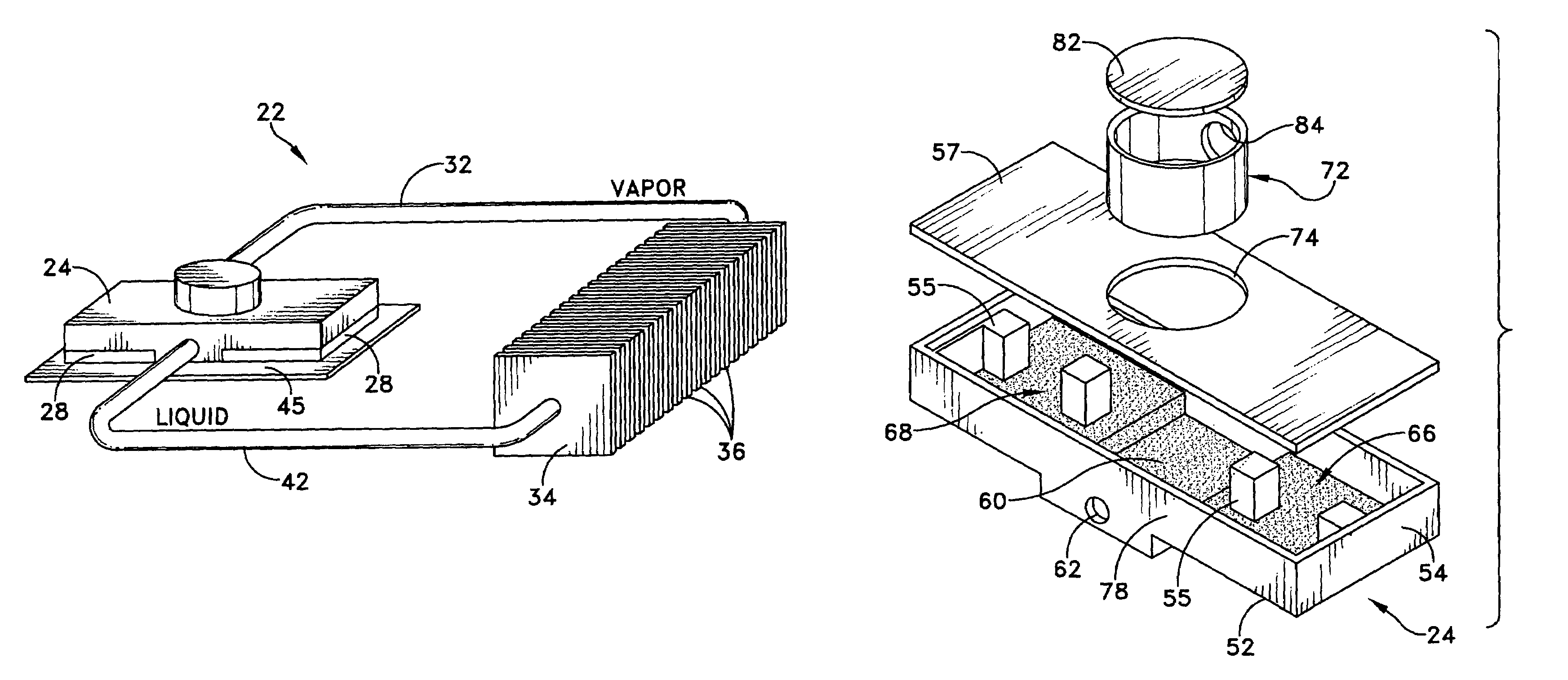
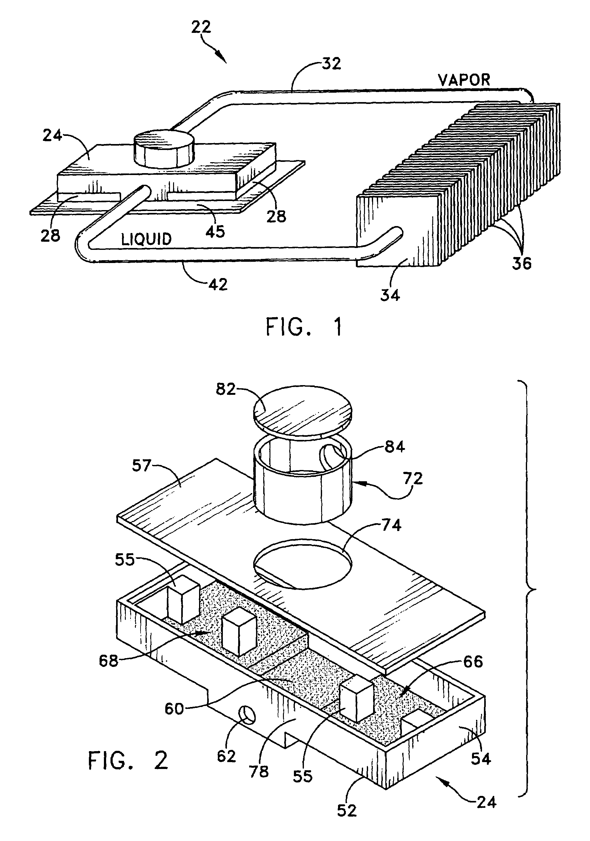
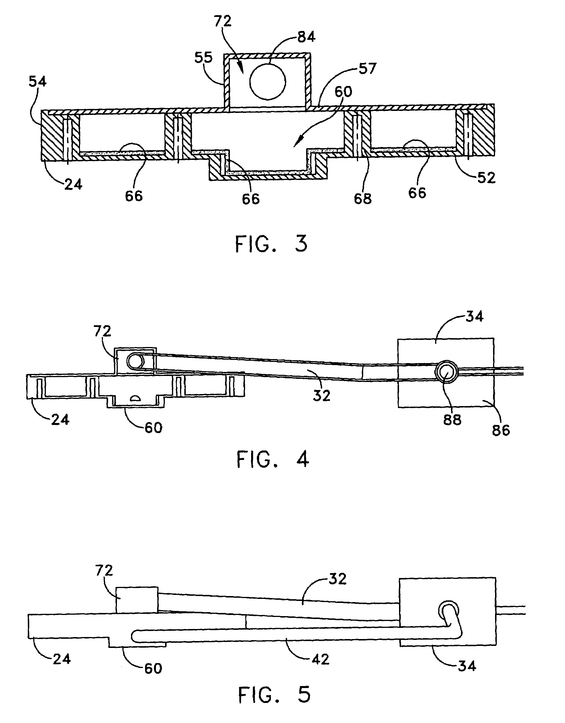
[0034]In convection heating, for example, heating of a vapor decreases its density and results in heated vapor currents with upward gradients; however heat and va...


PUM

PropertyMeasurementUnit
heat energyaaaaaaaaaa
thermally conductiveaaaaaaaaaa
temperaturesaaaaaaaaaa

Abstract

A heat sink or heat transfer device particularly for integrated circuits, uses a phase change working fluid in a cyclic flow path having at least one evaporator that serves multiple heat sources. The evaporator can be an integral vessel made of thermally conductive material to which the multiple heat sources are coupled, preferably at evaporation points that are placed on opposite sides of a fluid reservoir for the liquid phase of the working fluid that feeds the evaporation points via capillary flow through a picking material.

Description

FIELD OF THE INVENTION[0001]The invention relates to a fluid heat transfer loop having circulating coolant in an evaporator coupled to a heat source and a condenser coupled to a heat sink spaced from the heat source. More particularly the invention concerns a thermally-powered heat transfer loop, containing a phase change coolant, with an evaporator that couples plural heat sources, potentially at different operational temperatures, into a same circulating coolant loop.BACKGROUND OF THE INVENTION [0002]Thermal energy transfer loops, known as heat pipes, can transfer heat energy efficiently from a heat source to a sink. Circulation of the heat-transfer coolant in the loop advantageously can be driven simply by the heat energy that the loop dissipates. In loops having a coolant phase change, from liquid to vapor at an evaporator that is thermally coupled with the heat source, and from vapor to liquid at a condenser that has capacity to absorb heat energy, the phase changes store and r...

Claims


Application Information

Patent Timeline
Patent Type & Authority Patents(United States)
IPC IPC(8): F28D15/02H05K7/20B01D3/00F28D15/04
CPCF28D15/0266F28D15/043B01D3/007F28F3/12
Inventor WENGER, TODD M.
Owner THERMAL
Why Eureka
Try Eureka