
Self passivating transition metal nitride printhead heaters

a transition metal nitride and printhead technology, applied in printing, inking apparatus, other printing apparatus, etc., can solve the problems of heater element burnout, low resistivity suitable for inkjet heaters, and inability to self-passivate tin

Inactive Publication Date: 2008-10-07
MEMJET TECH LTD +1
View PDF6 Cites 43 Cited by
  • Summary
  • Abstract
  • Description
  • Claims
  • Application Information

AI Technical Summary

Benefits of technology

The solution enables the inkjet printhead to eject more than one billion drops with improved oxidation resistance, reduced energy requirements, and increased nozzle density, leading to higher print resolution and speed while minimizing manufacturing costs.

Problems solved by technology

The metallic bonding in some transition metal nitrides such as TiN and TaN can also result in low resistivity suitable for inkjet heaters.
However, TiN is not self passivating as it oxidises readily.
Testing has shown that nozzles using uncoated TiN heaters ejected no more than a few tens of thousands of droplets before the heater went open circuit (that is, the heater element burned out due to oxidative failure).
TaN was also found to have inadequate oxidation resistance.

Method used


Image

  • Self passivating transition metal nitride printhead heaters
  • Self passivating transition metal nitride printhead heaters
  • Self passivating transition metal nitride printhead heaters

Examples


Embodiment Construction

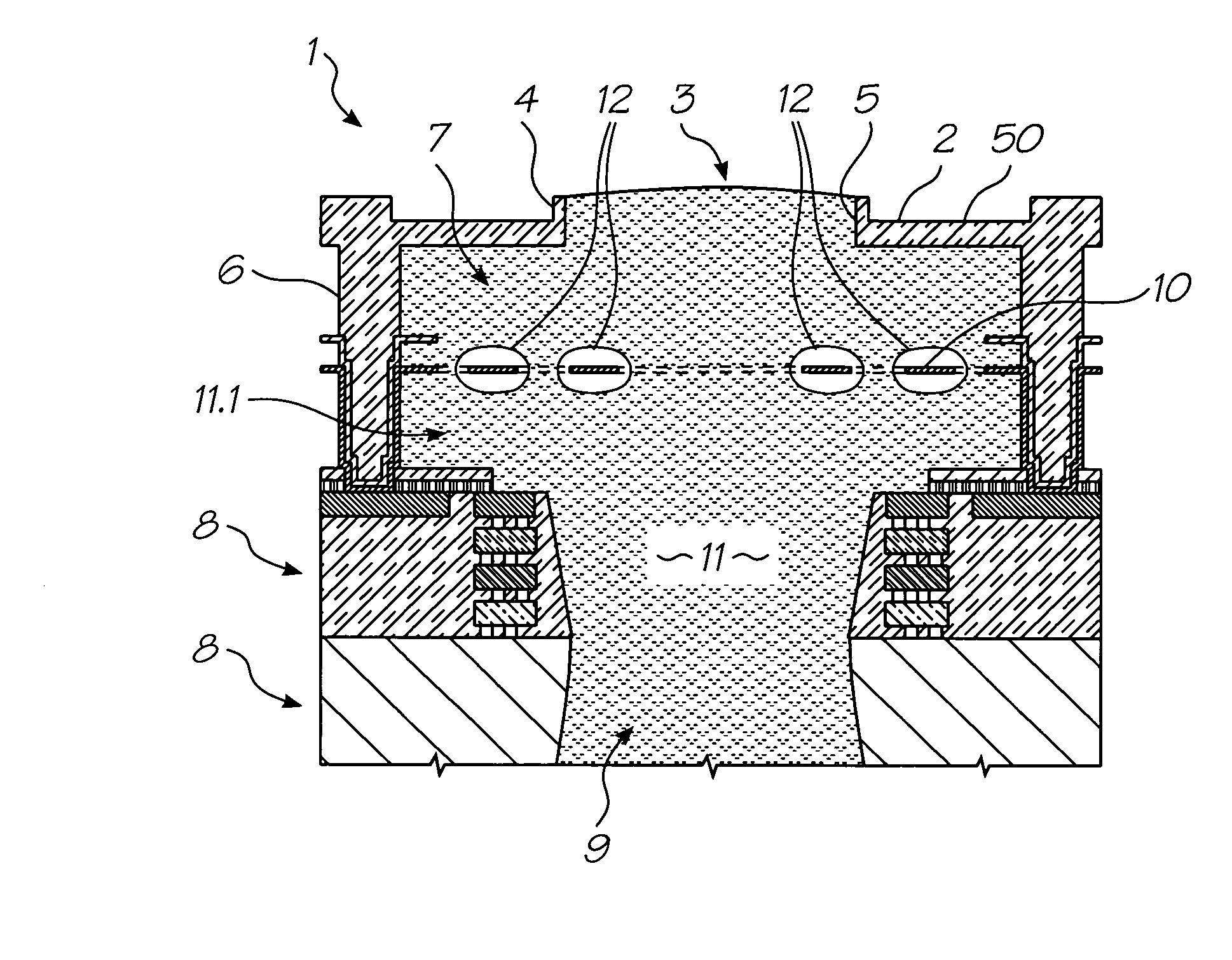
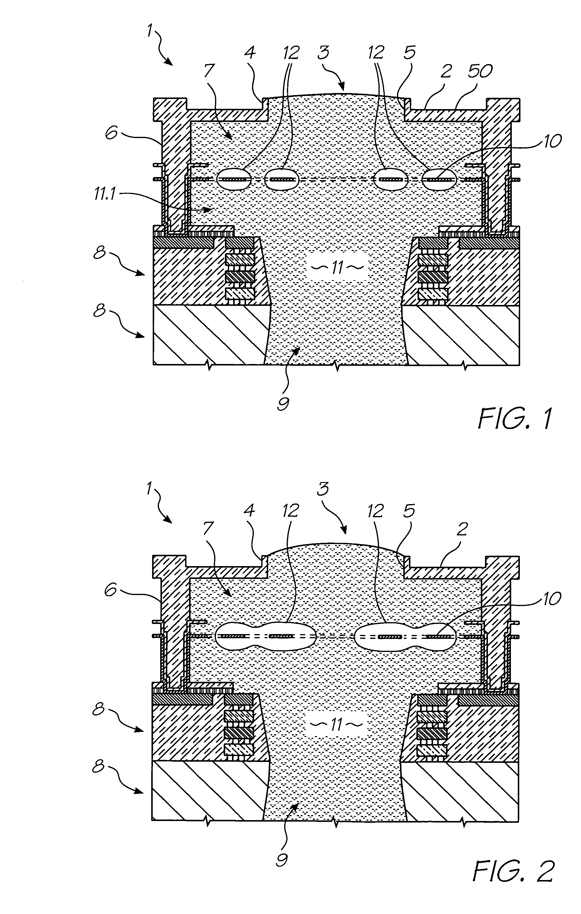
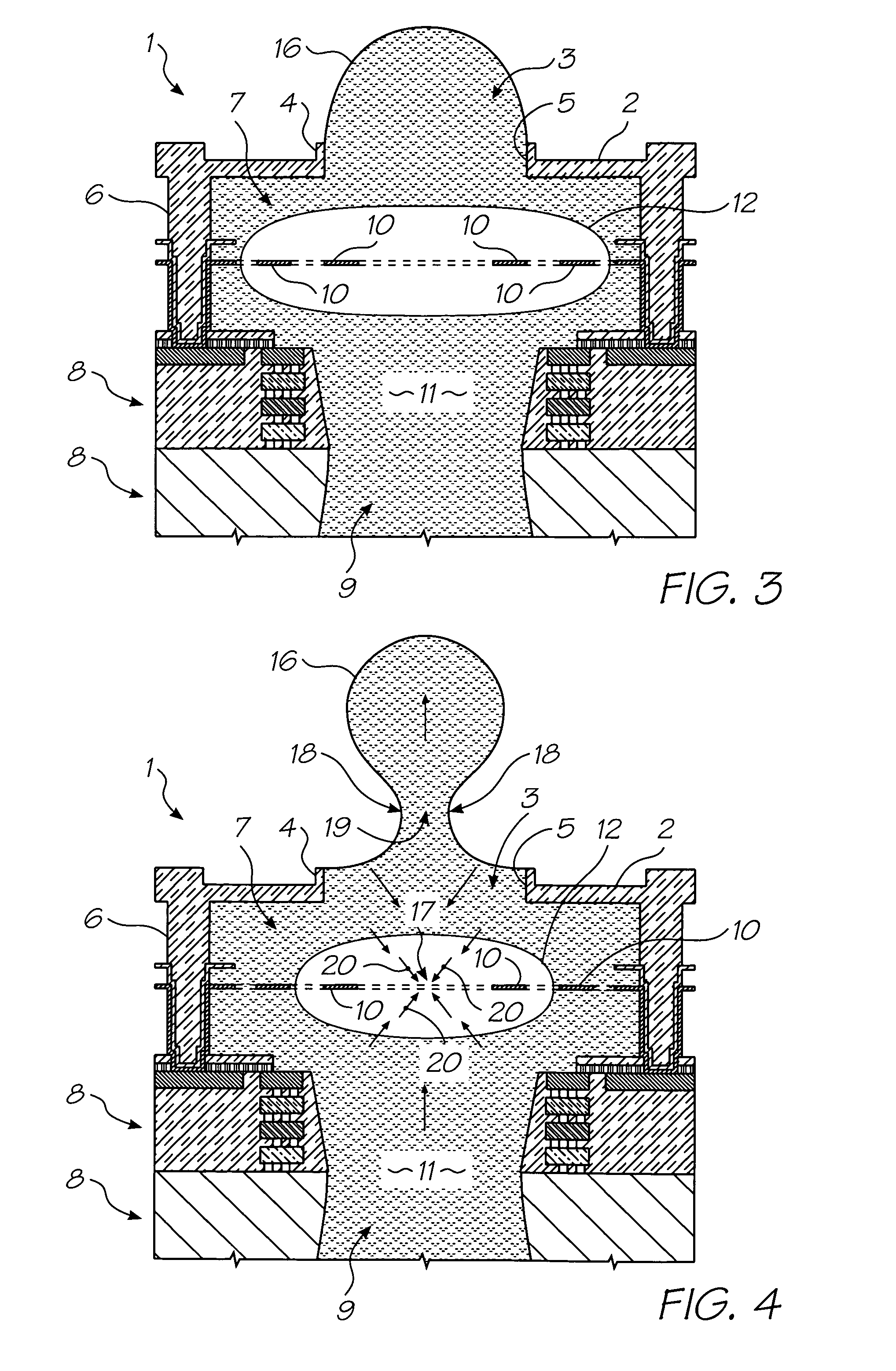
[0232]In the description than follows, corresponding reference numerals, or corresponding prefixes of reference numerals (i.e. the parts of the reference numerals appearing before a point mark) which are used in different figures relate to corresponding parts. Where there are corresponding prefixes and differing suffixes to the reference numerals, these indicate different specific embodiments of corresponding parts.

Overview of the Invention and General Discussion of Operation

[0233]With reference to FIGS. 1 to 4, the unit cell 1 of a printhead according to an embodiment of the invention comprises a nozzle plate 2 with nozzles 3 therein, the nozzles having nozzle rims 4, and apertures 5 extending through the nozzle plate. The nozzle plate 2 is plasma etched from a silicon nitride structure which is deposited, by way of chemical vapor deposition (CVD), over a sacrificial material which is subsequently etched.

[0234]The printhead also includes, with respect to each nozzle 3, side walls 6...


PUM

PropertyMeasurementUnit
actuation energyaaaaaaaaaa
surface areaaaaaaaaaaa
viscosityaaaaaaaaaa

Abstract

A thermal inkjet printhead with heater elements formed from a self passivating transition metal nitride, but it oxidizes readily. By introducing an additive that allows the metal nitride to self passivate, the heater element forms a surface oxide layer, where the oxide has a low diffusion coefficient for oxygen so as to provide a barrier to further oxidation. With enhanced oxidation resistance, coatings to protect the heater from oxidative failure become unnecessary and the energy needed to form a bubble is reduced.

Description

FIELD OF THE INVENTION[0001]The present invention relates to inkjet printers and in particular, inkjet printheads that generate vapor bubbles to eject droplets of ink.CO-PENDING APPLICATIONS[0002]The following applications have been filed by the Applicant simultaneously with the present application:[0003]11 / 09730811 / 097309724687611 / 09731011 / 09721311 / 097212[0004]The disclosures of these co-pending applications are incorporated herein by reference. The above applications have been identified by their filing docket number, which will be substituted with the corresponding application number, once assigned.CROSS REFERENCES TO RELATED APPLICATIONS[0005]The following patents or patent applications filed by the applicant or assignee of the present invention are hereby incorporated by cross-reference.[0006]67509016476863678833611 / 00378611 / 00361611 / 00341811 / 00333411 / 00360011 / 00340411 / 00341911 / 00370011 / 00360111 / 003618722914811 / 00333711 / 00369811 / 003420698401711 / 00369911 / 07147311 / 00346311 / 003701...

Claims


Application Information

Patent Timeline
Patent Type & Authority Patents(United States)
IPC IPC(8): B41J2/05B41J29/38
CPCB41J2/1412B41J2/1601B41J2/1603B41J2/1628B41J2/1631B41J2/1639B41J2/1642B41J2/1645B41J2/1646B41J2002/1437B41J2002/14475B41J2002/14491B41J2202/03B41J2202/20
Inventor SILVERBROOK, KIANORTH, ANGUS JOHNMCAVOY, GREGORY JOHNFISHBURN, JENNIFER MIA
Owner MEMJET TECH LTD
Learn More