Pump health monitoring

a technology of pump health and monitoring method, applied in the direction of instruments, structural/machine measurement, turbine/propulsion fuel control, etc., can solve the problems of pump wear at different rates, leakage becomes progressively worse,

Active Publication Date: 2008-10-07
GOODRICH CONTROL SYST LTD
View PDF8 Cites 15 Cited by
  • Summary
  • Abstract
  • Description
  • Claims
  • Application Information

AI Technical Summary

Problems solved by technology

Such leakage becomes progressively worse with time as a result of wear of the internal components of the pump.
Clearly pumps will wear at different rates dependent upon their usage and the ambient conditions in which they operate.

Method used


Image

  • Pump health monitoring
  • Pump health monitoring
  • Pump health monitoring

Examples


Embodiment Construction

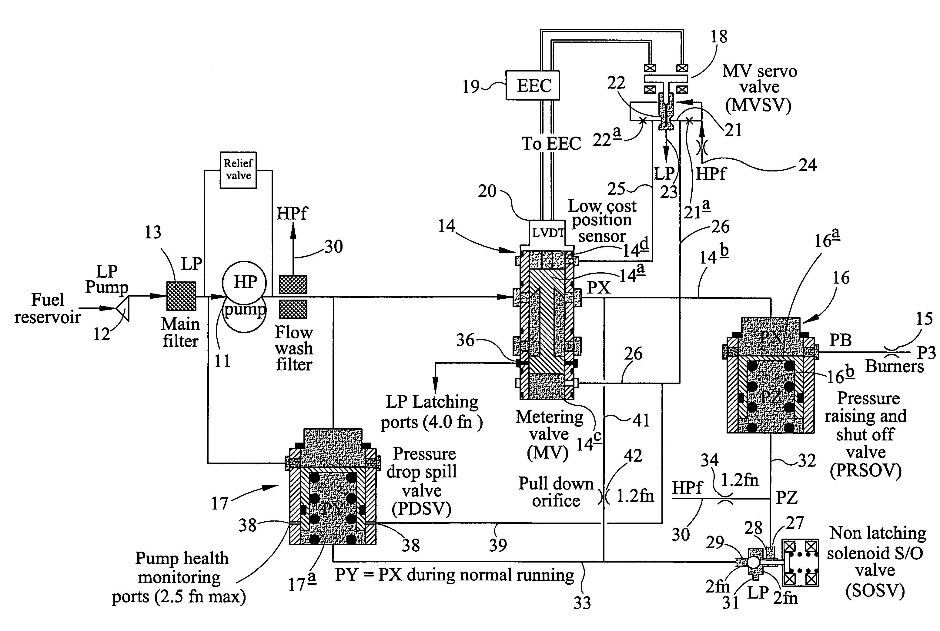
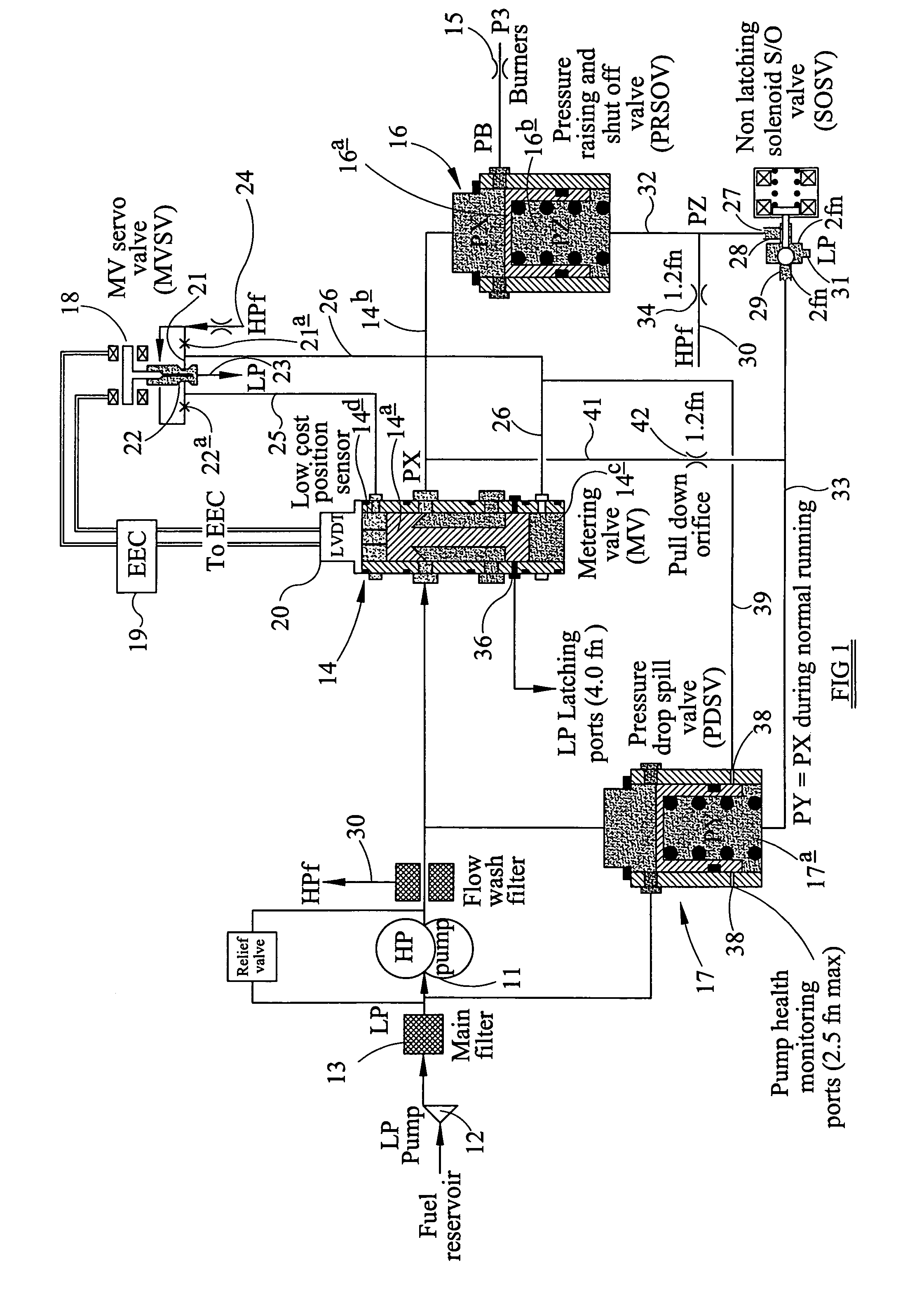
[0022]In FIG. 1 it can be seen that a high pressure positive displacement pump 11, conveniently a gear pump, is supplied with fuel from a reservoir by a low pressure pump 12 through a main fuel flow filter 13. A fuel metering unit (FMU) including a fuel metering valve 14 controls flow of fuel from the high pressure output side of the pump 11 to the burners 15 of the gas turbine engine, the FMU also including a Pressure Raising and Shut Off Valve (PRSOV) 16, and a Pressure Drop Spill Valve (PDSV) 17 which can route high pressure output from the pump 11 back to the low pressure inlet of the pump 11 as necessary.

[0023]In general terms the system described so far is conventional. An electrically operated metering valve servo valve 18 controls operation of the valve 14 in response to control signals from an electronic engine controller (EEC) 19 which receives electronic data representative inter alia of the position of the metering member 14a of the valve 14 and the speed of operation of...


PUM


Abstract

A method of monitoring the health of a positive displacement hydraulic pump comprising the steps of:establishing a flow path having a known flow number between a high pressure outlet line of the pump (and a low pressure line of the system;progressively changing the speed of operation of the pump; and,noting the speed of operation of the pump at a parameter responsive to the output pressure of the pump changes in response to said change in rotational speed of the pump.

Description

TECHNICAL FIELD[0001]This invention relates to a method of monitoring the health of a pump in a fuel supply system, conveniently but not exclusively, a fuel supply system for a gas turbine engine of an aircraft.[0002]Although the invention may find application outside of the field of aircraft gas turbine engine fuel supply systems, the problem which the invention solves, and an understanding of the invention can best be appreciated by describing the invention in relation to an aircraft engine fuel supply system.BACKGROUND ART[0003]In an aircraft gas turbine engine fuel supply system it is common to use a positive displacement pump such as a gear pump or a piston pump to provide fuel at high pressure for supply, through a fuel metering unit (FMU), to the burners of the gas turbine engine. Positive displacement pumps all have an individual internal leakage characteristic in that some proportion of the high pressure output flow of the pump leaks back to the low pressure inlet side of t...

Claims


Application Information

Patent Timeline
Patent Type & Authority Patents(United States)
IPC IPC(8): F04B43/12F02G3/00G01M3/02F02C7/22F02C9/30F04B51/00F04C14/08
CPCF02C7/22F02C9/30F04B51/00F04C14/08F04C2270/80
Inventor GRIFFITHS, MICHAEL
Owner GOODRICH CONTROL SYST LTD
Why Eureka
Try Eureka