
Coupling loop

a wireless sensor and loop technology, applied in the field of communication with a wireless sensor, can solve the problems of increasing and the current imaging modalities of angiography and ct scan are not always sensitive enough to detect endoleaks or stent graft failure, so as to increase the chance of aneurysm rupture and prevent rupture.

Active Publication Date: 2008-10-07
ST JUDE MEDICAL LUXEMBOURG HLDG II S A R L SJM LUX II
View PDF31 Cites 78 Cited by
  • Summary
  • Abstract
  • Description
  • Claims
  • Application Information

AI Technical Summary

Benefits of technology

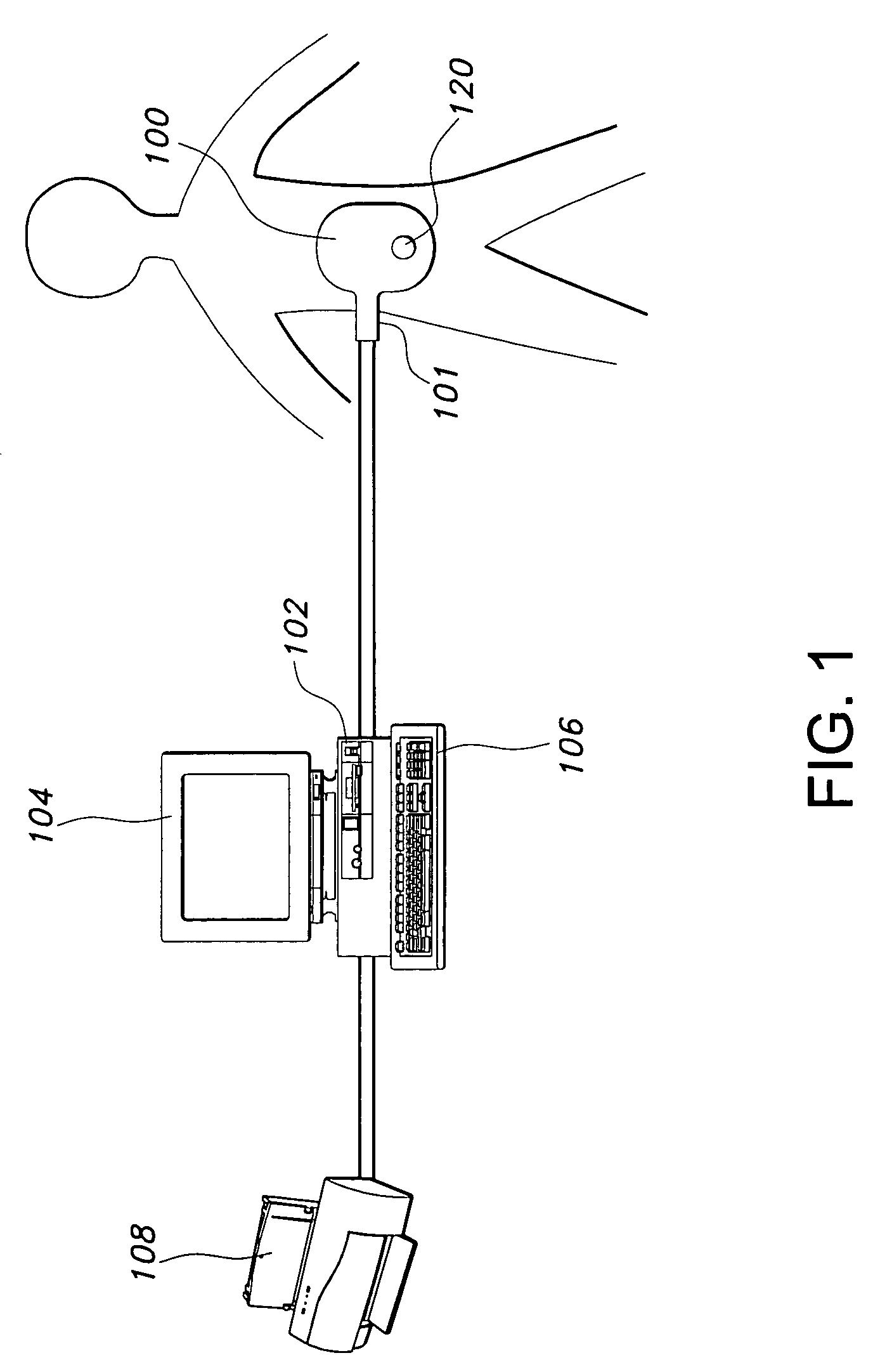
[0009]The primary goal of aneurysm treatment is to depressurize the sac and to prevent rupture. Endoleaks, whether occurring intraoperatively or postoperatively, can allow the aneurysmal sac to remain pressurized and therefore, increase the chance of aneurysm rupture. The current imaging modalities angiography and CT scan are not always sensitive enough to detect endoleaks or stent graft failure. Intrasac pressure measurements provide a direct assessment of sac exclusion from circulation and may therefore offer intraoperative and post operative surveillance advantages that indirect imaging studies do not.
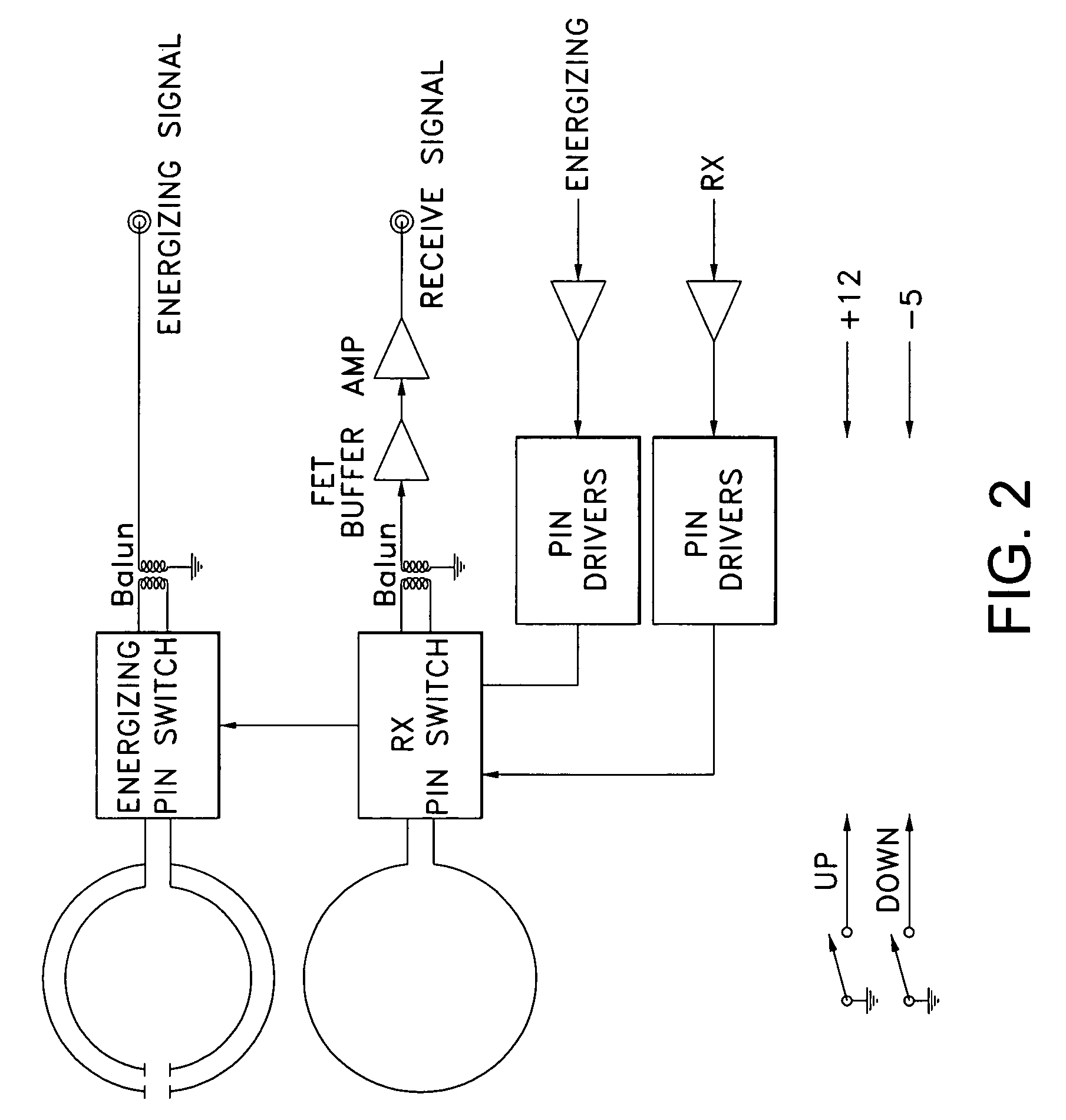
[0012]The loops are connected to a base unit that generates the energizing signal and processes the sensor signal via a cable assembly. The cable assembly provides maximum isolation between the energizing signal and the sensor signal by maximizing the distance between the coaxial cables that carry the signals and maintaining the relative positions of the coaxial cables throughout the cable assembly. In one aspect of the invention, the coaxial cables are positioned on opposite sides of an internal cable, approximately 180 degrees apart. Shielding is also used to isolate the energizing signal from the sensor signal. In one aspect of the invention, additional shielding is provided around each of the coaxial cables.
[0013]Orientation features are provided for positioning the coupling loop relative to the sensor to maximize the coupling between the sensor and the coupling loop. The orientation features facilitate the placement of the sensor during implantation and the coupling loop during follow-up examinations. A physician typically uses fluoroscopy to implant the sensor in the patient. The sensor needs to be implanted in the proper anatomical location, e.g. within the aneurysm sac, and needs to be oriented to facilitate maximum coupling between the sensor and the coupling loop. In one aspect of the invention, the sensor and the coupling loop include orientation features that are visible using fluoroscopy or another medical imaging technology. The orientation features on the sensor include radiopaque markings and the orientation features on the coupling loop include a pattern in the ribbing of the housing for the loop.

Problems solved by technology

Endoleaks, whether occurring intraoperatively or postoperatively, can allow the aneurysmal sac to remain pressurized and therefore, increase the chance of aneurysm rupture.
The current imaging modalities angiography and CT scan are not always sensitive enough to detect endoleaks or stent graft failure.

Method used


Image

  • Coupling loop
  • Coupling loop
  • Coupling loop

Examples


Embodiment Construction

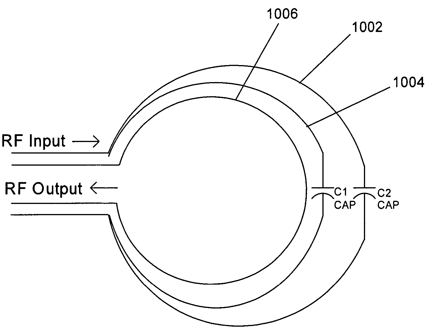
[0034]The present invention is directed towards a coupling loop and cable assembly that supports precise sampling of a low power, quickly dissipating signal (the sensor signal) and that isolates the energizing signal used to excite the sensor from the sensor signal. The present invention also provides orientation features for positioning the coupling loop relative to the sensor to maximize the coupling of the sensor signal. Briefly described, the coupling loop includes multiple loops. Preferably two stagger-tuned loops are used for transmitting the energizing signal to the sensor and an un-tuned loop is used for receiving the sensor signal from the sensor. The un-tuned loop is connected to a very high input impedance to minimize the impact of the inductance of the loop. A cable attached to the coupling loop provides maximum isolation between the energizing signal and the sensor signal by maximizing the distance between the coaxial cables that carry the signals and maintaining the re...


PUM


Abstract

A coupling loop or antenna is provided that can be used with a system that determines the resonant frequency of a sensor by adjusting the phase and frequency of an energizing signal until the frequency of the energizing signal matches the resonant frequency of the sensor. The coupling loop includes multiple loops. Preferably two tuned loops are used for transmitting the energizing signal to the sensor and an un-tuned loop is used for receiving the sensor signal from the sensor. Orientation features on the housing for the coupling loop and the sensor are provided to assist in positioning the coupling loop relative to the sensor to maximize the coupling between the sensor signal and the coupling loop.

Description

RELATED APPLICATIONS[0001]This application is a continuation-in-part of U.S. application Ser. No. 11 / 105,294 entitled “Communicating with an Implanted Wireless Sensor” filed Apr. 13, 2005 now U.S. Pat. No. 7,245,117, which claims priority to U.S. Provisional Application No. 60 / 623,959 entitled “Communicating with an Implanted Wireless Sensor” filed Nov. 1, 2004. This application also claims priority to U.S. Provisional Application No. 60 / 697,867 entitled “Cable with Isolated Components” filed Jul. 8, 2005; U.S. Provisional Application No. 60 / 697,878 entitled “Antenna Sensor Location” filed Jul. 8, 2005 and U.S. Provisional Application No. 60 / 707,094 entitled “Broadband Transmit and Receive Antennas” filed Aug. 10, 2005. This application is related to U.S. application Ser. No. 11 / 276,571 entitled “Communicating with an Implanted Wireless Sensor” filed Mar. 6, 2006. All of the foregoing applications are incorporated herein by reference.TECHNICAL FIELD[0002]The present invention is dir...

Claims


Application Information

Patent Timeline
Patent Type & Authority Patents(United States)
IPC IPC(8): G01R27/28A61N1/00H01Q21/00
CPCA61B5/0031A61B5/02014A61B5/064A61B5/07H01B11/20H04B5/0043A61B2560/0219Y10S128/903H04B5/73
Inventor ELLIS, MICHAELKROH, JASONMILLER, DONALD
Owner ST JUDE MEDICAL LUXEMBOURG HLDG II S A R L SJM LUX II
Learn More