Image processing method

Active Publication Date: 2008-10-07
CANON KK +1
View PDF32 Cites 42 Cited by
  • Summary
  • Abstract
  • Description
  • Claims
  • Application Information

AI Technical Summary

Benefits of technology

[0019]The present invention has been made to solve the aforementioned problems, and has as its object

Problems solved by technology

In addition to various kinds of noise mentioned above, a factor that especially impairs the image quality is noise (to be referred to as “low-frequency noise” hereinafter) which is generated in a low-frequency range and is conspicuously observed in an image sensed by a digital camera or the like.
This low-frequency noise often results from the sensitivity of a CCD or CMOS sensor as a solid-state image sensing element.
Hence, in a digital camera which has a large number of pixels within a small area, the amount of light per unit pixel consequently decreases, and the sensitivity lowers, thus producing noise.
Some digital cameras often produce false colors.
Since block distortion is noise that generates block-like steps which are different from signal components in a flat region, these steps can become hard to be visually recognized by moderating the slope of the steps.
However, none of the above prior arts are effective for low-frequency noise such as speckle noise or the like.
Hence, low-frequency noise cannot be reduced.
However, low-frequency noise is coupled noise in which pixel values

Method used


Image

  • Image processing method
  • Image processing method
  • Image processing method

Examples


Example

First Embodiment

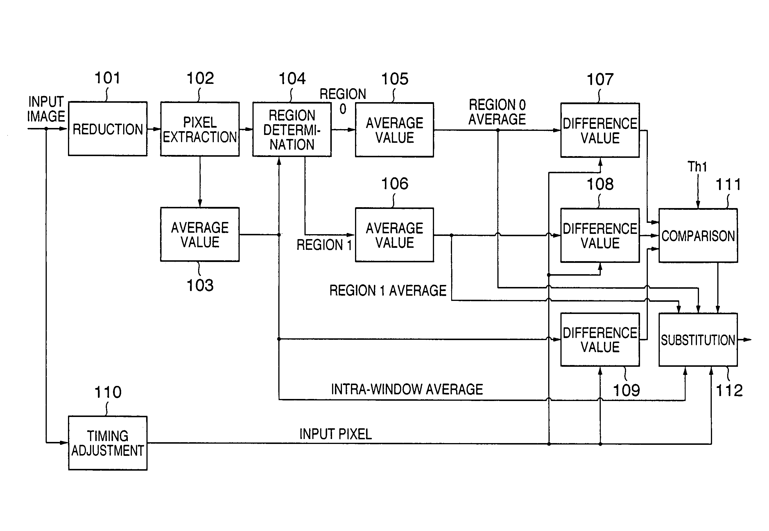
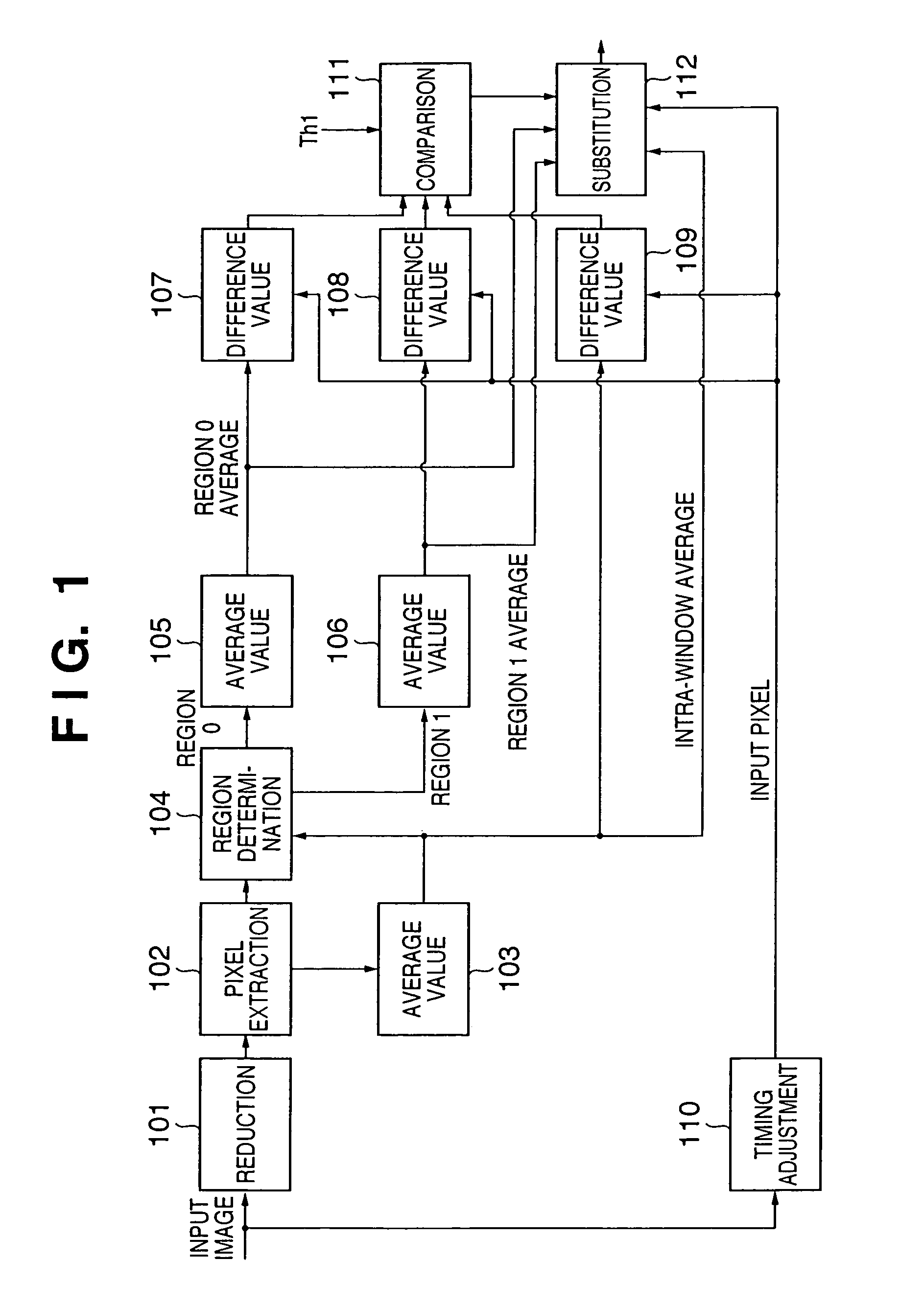
[0083]FIG. 1 is a block diagram showing the arrangement of an image processing apparatus according to the first embodiment. Referring to FIG. 1, reference numeral 101 denotes an image reduction unit, which reduces an input image to a predetermined scale (e.g., ¼). Reference numeral 102 denotes a pixel extraction unit, which extracts pixels to an n×m (m and n are integers) rectangular pattern (window) having an input pixel position as the center from the reduced image. Reference numeral 103 denotes an intra-window average value calculation unit, which generates an average value of the extracted pixel values in the window. Reference numeral 104 denotes a region determination unit which compares, e.g., downsize pixel values in the window with the intra-window average value, and determines that pixels whose pixel values are equal to or smaller than the intra-window average value belong to region 0, or determines that other pixels belong to region 1. Reference numeral 10...

Example

Second Embodiment

[0100]The second embodiment of the present invention will be described in detail hereinafter with reference to the accompanying drawings.

[0101]In the second-embodiment, in a window in which the difference between the average values of two regions is small, an intra-window average value is determined as substitute data.

[0102]FIG. 5 is a block diagram showing the arrangement of an image processing apparatus according to the second embodiment. Referring to FIG. 5, reference numerals 501 to 506 and 507 denote units which execute the same processes as those of the units 101 to 106 and 110 shown in FIG. 1 in the first embodiment, and a detailed description thereof will be omitted. Reference numeral 508 denotes an average value calculation unit; 509, 513, and 514, comparison units; 510 and 511, selection units; 512, a subtraction unit; 515, a difference value generation unit; and 516, a pixel substitution unit. Only differences from the first embodiment will be explained ...

Example

Third Embodiment

[0111]The third embodiment of the present invention will be described in detail hereinafter with reference to the accompanying drawings.

[0112]In the third embodiment, in the substitute data generation process explained in the second embodiment, the average value of two regions is output as substitute data in accordance with a random number generated by a random number generation unit.

[0113]FIG. 8 is a block diagram showing the arrangement of an image processing apparatus according to the third embodiment. Referring to FIG. 8, reference numerals 801 to 807 and 810 to 812 denote units which execute the same processes as those of the units 501 to 507 and 514 to 516 shown in FIG. 5 in the second embodiment, and a detailed description thereof will be omitted. Reference numeral 808 denotes a random number generation unit; and 809, a selection unit. Only differences from the second embodiment will be explained below.

[0114]The random number generation unit 808 generates a p...


PUM


Abstract

Pixels in a window, which corresponds to the position of an input pixel and has a predetermined size, are extracted from a reduced image obtained by reducing an input image to a predetermined scale. Substitute data used to substitute the value of the input pixel is generated based on the extracted pixels in the window. The difference value between the substitute data and input pixel value is calculated and is compared with a first threshold value. When the difference value is smaller than the first threshold value, the input pixel value is substituted by the substitute data. Thus, low-frequency noise reduction can be attained using a minimum required memory size while suppressing adverse effects such as a resolution drop and the like.

Description

FIELD OF THE INVENTION[0001]The present invention relates to a technique for reducing noise of an input multi-valued image.BACKGROUND OF THE INVENTION[0002]Conventionally, a technique for removing noise components from a digital image on which noise components that are different from signal components are superposed has been studied. The characteristics of noise are diverse depending on their generation factors, and noise removal methods suited to those characteristics have been proposed. For example, when an image input device such as a digital camera, image scanner, or the like is assumed, noise components are roughly categorized into noise which depends on the input device characteristics of a solid-state image sensing element or the like and input conditions such as an image sensing mode, scene, or the like, and has already been superposed on a photoelectrically converted analog original signal, and noise which is superposed via various digital signal processes after the analog ...

Claims


Application Information

Patent Timeline
IPC IPC(8): H04N5/21H04N5/213H04N5/217H04N7/26
CPCH04N5/21H04N19/86H04N5/357H04N25/60
Inventor ISHIKAWA, HISASHIFUJIWARA, MAKOTOKATO, MASAOSUWA, TETSUYAGOTO, FUMITAKAIMAFUKU, KAZUYA
Owner CANON KK
Why Eureka
Try Eureka