Thermoelectric cooling device arrays

Active Publication Date: 2008-10-14
ORACLE INT CORP
View PDF42 Cites 62 Cited by
  • Summary
  • Abstract
  • Description
  • Claims
  • Application Information

AI Technical Summary

Benefits of technology

[0008]In some embodiments, temperature data for areas on the chip or for separate electronic components may be determined using one or more thermal sensors. The temperature data may be sent to a controller, and the controller may determine an appropriate response for the TEC devices in the TEC device array ne

Problems solved by technology

Chips, such as microprocessors, may generate significant heat during operation.
High temperatures may reduce the lifespan of these chips, and, therefore, the generated heat may need to be dispersed to keep the

Method used


Image

  • Thermoelectric cooling device arrays
  • Thermoelectric cooling device arrays
  • Thermoelectric cooling device arrays

Examples


Embodiment Construction

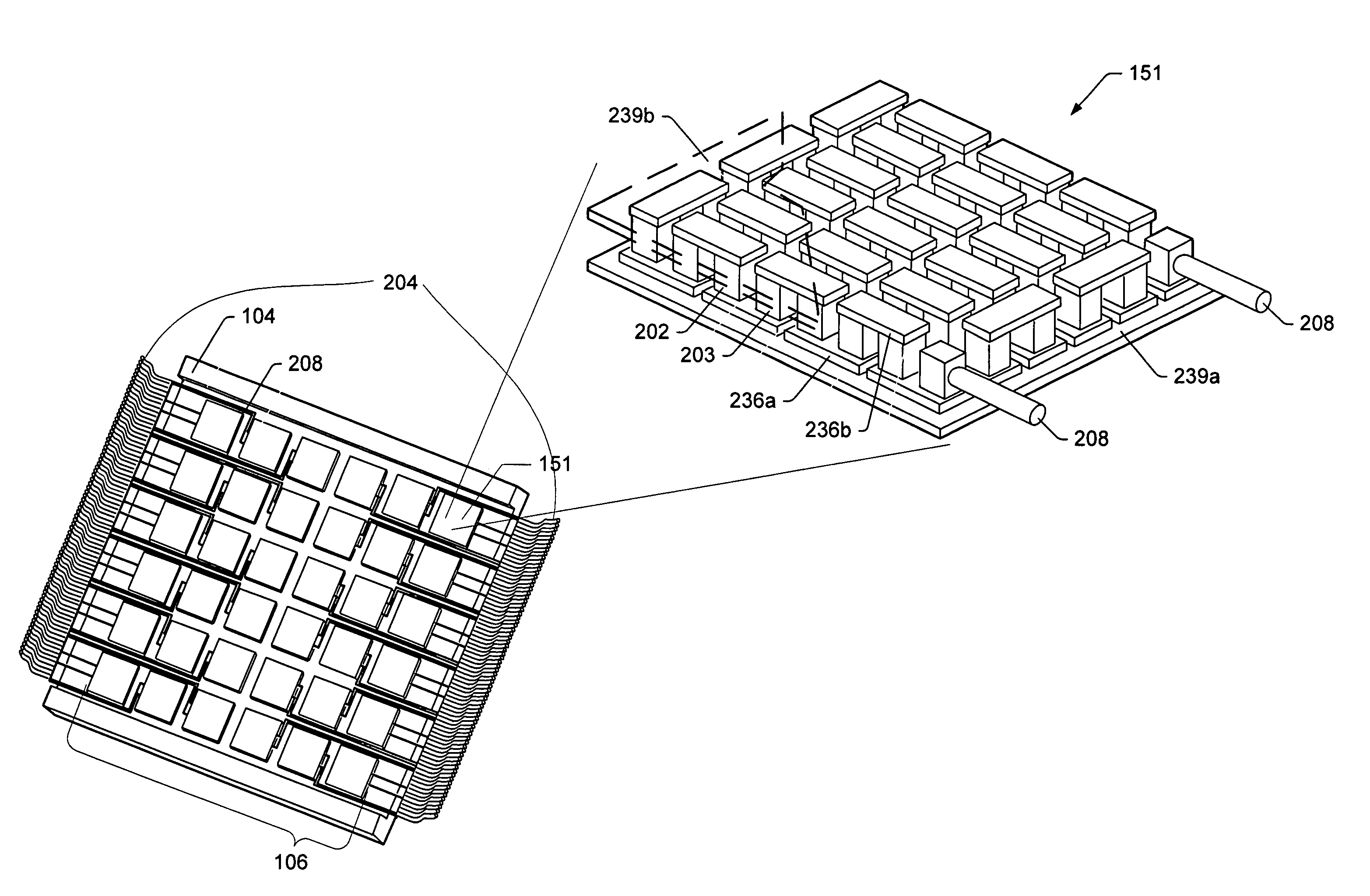
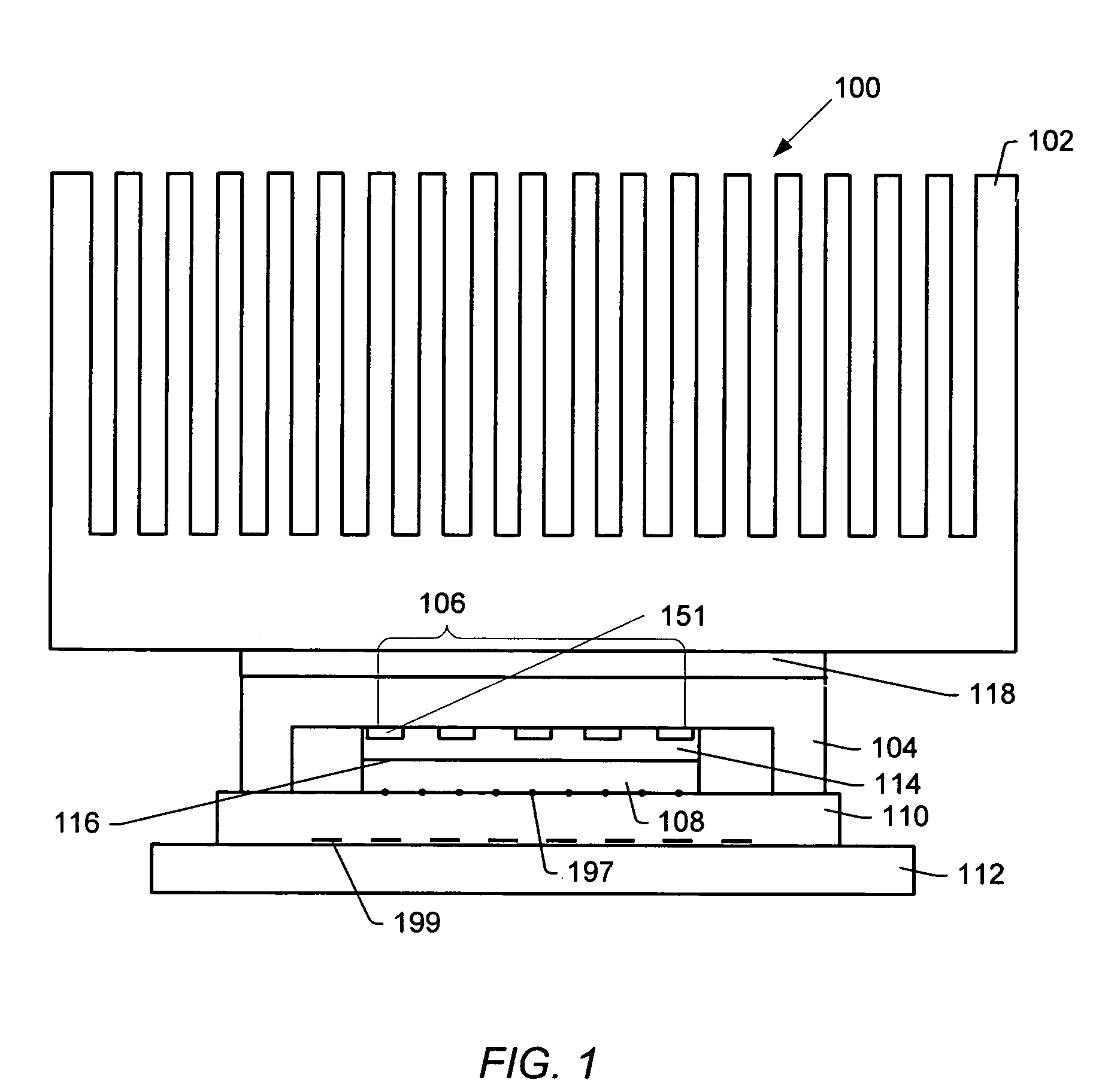
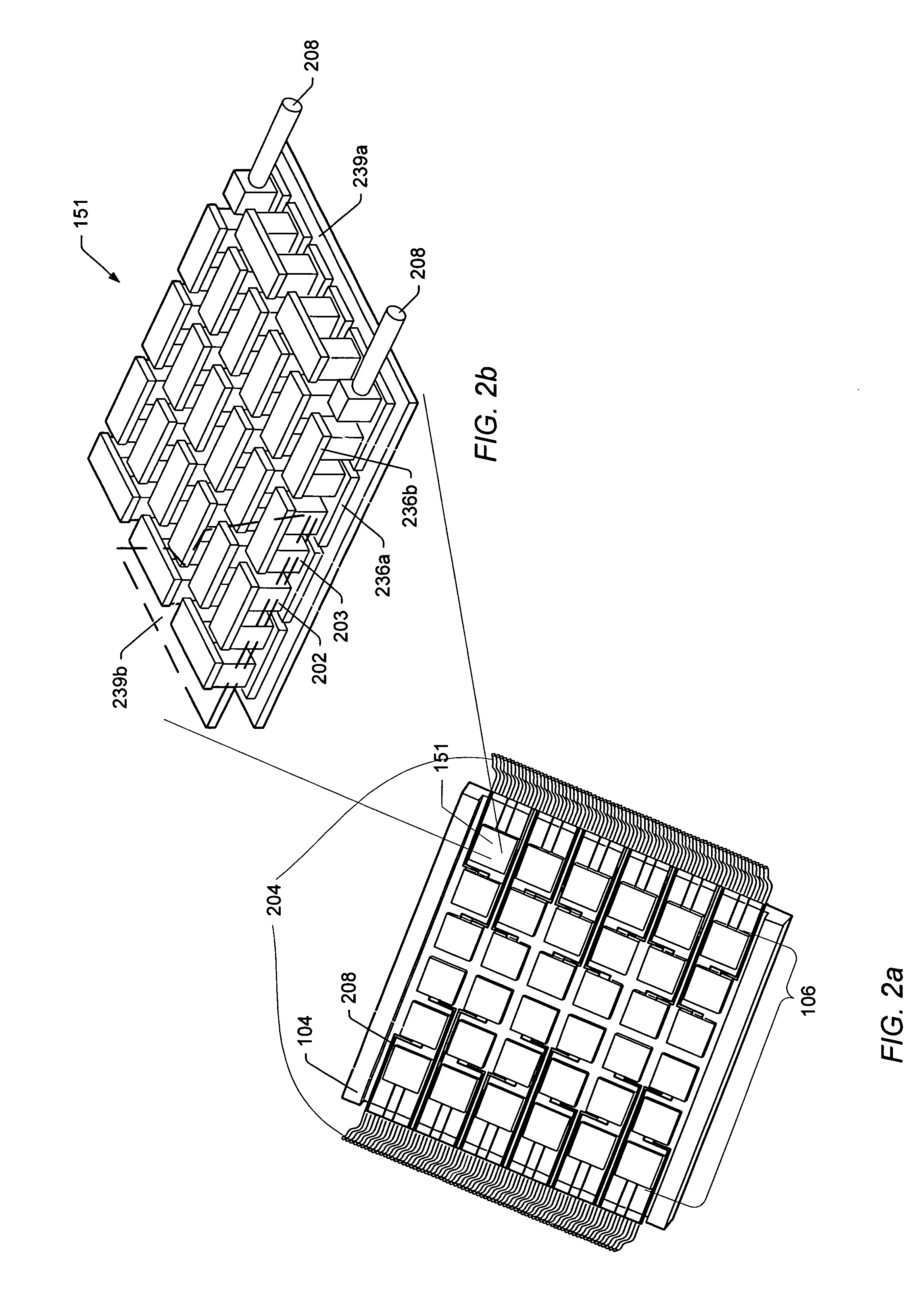
[0024]FIG. 1 illustrates an embodiment of a TEC device array 106 (which includes TEC devices 151) coupled to a chip 108 and a heat sink 102. The TEC device array 106 may include multiple TEC devices 151 arranged in a uniform or non-uniform pattern for removing heat from the chip 108. TEC device array 106 may include multiple TEC devices 151 of similar or different sizes. TEC device array 106 refers generally to an array of TEC devices 151. Different embodiments of TEC devices 151 and TEC device arrays 106 are presented throughout with different letter designators (e.g., TEC device 151a,b and TEC device arrays 106a,b). It is noted that different lettered embodiments of the TEC devices 151 and TEC device arrays 106 may be of similar size and configuration as other TEC devices 151 and TEC device arrays 106 presented (or may be different).

[0025]In some embodiments, the chip 108 may be, for example, an electronic element such as a microprocessor, a digital signal processor, or a graphics...


PUM


Abstract

In various embodiments, a TEC device array may be coupled to a chip and a heat sink to cool the chip. The TEC device array may include multiple TEC devices separately controlled to provide different cooling rates at different points in the TEC device array coupled to the chip. In some embodiments, temperature data for areas on the chip or for separate electronic components may be determined using one or more thermal sensors and then sent to a controller. The controller may then determine an appropriate response for the TEC devices in the TEC device array near the area of the thermal sensor(s). The controller may thus control the cooling rates (which may be different) of several TEC devices in the TEC device array.

Description

BACKGROUND OF THE INVENTION[0001]1. Field of the Invention[0002]The present invention relates generally to electronic cooling and, more specifically, to thermoelectric cooling devices.[0003]2. Description of the Related Art[0004]Chips, such as microprocessors, may generate significant heat during operation. High temperatures may reduce the lifespan of these chips, and, therefore, the generated heat may need to be dispersed to keep the operating temperature of the chips within acceptable limits. Heat sinks may be coupled to chips to absorb heat through the heat sink base and disperse the heat through their fins. In addition, a single thermoelectric cooling (TEC) device has been used to pump heat away from the chip.[0005]The basic concept behind thermoelectric cooling technology is the Peltier effect. The Peltier effect occurs whenever electrical current flows through two dissimilar conductors. Depending on the direction of current flow, the junction of the two conductors will either ...

Claims


Application Information

Patent Timeline
IPC IPC(8): H01L23/34
CPCH01L23/34H01L23/38H01L35/30F25B2321/021H01L2924/0002H01L2924/00H10N10/13
Inventor OUYANG, CHIEN
Owner ORACLE INT CORP
Why Eureka
Try Eureka