Inverter apparatus

a technology of inverter and apparatus, which is applied in the direction of electric controllers, dynamo-electric converter control, instruments, etc., can solve the problems of increasing processing load, deviation from sine wave to become significant, increasing cost, etc., and achieves torque ripple reduction, current ripple reduction, and efficiency increase

Active Publication Date: 2008-10-14
MITSUBISHI ELECTRIC CORP
View PDF8 Cites 8 Cited by
  • Summary
  • Abstract
  • Description
  • Claims
  • Application Information

AI Technical Summary

Benefits of technology

[0012]According to the present invention, the output-voltage command value in which only the phase advances is updated a plurality of times within a calculation period. Therefore, even if there are a small number of calculation periods in the cycle of a fundamental wave of an output voltage, it is possible to obtain an output voltage with a waveform closer to the sine wave. Therefore, the current ripple is reduced more as compared with the conventional technology, thus achieving torque ripple reduction and efficiency increase. Furthermore, a CPU that calculates the output voltage command only needs to add a function of calculating a plurality of output-voltage command values in which only the phase advances. Therefore, the processing load of the CPU can be reduced, thus, there is no need to use an expensive CPU.

Problems solved by technology

To implement this, in the former case, a CPU that calculates an output voltage command needs to be upgraded, which causes an increase in cost.
In the latter case, the processing load increases.
Therefore, in the conventional technology, it becomes difficult to approximate a fine curve of the sine wave, which causes the deviation from the sine wave to become significant.

Method used


Image

  • Inverter apparatus
  • Inverter apparatus
  • Inverter apparatus

Examples


Embodiment Construction

[0020]Exemplary embodiments of an inverter device according to the present invention are explained in detail with reference to the accompanying drawings.

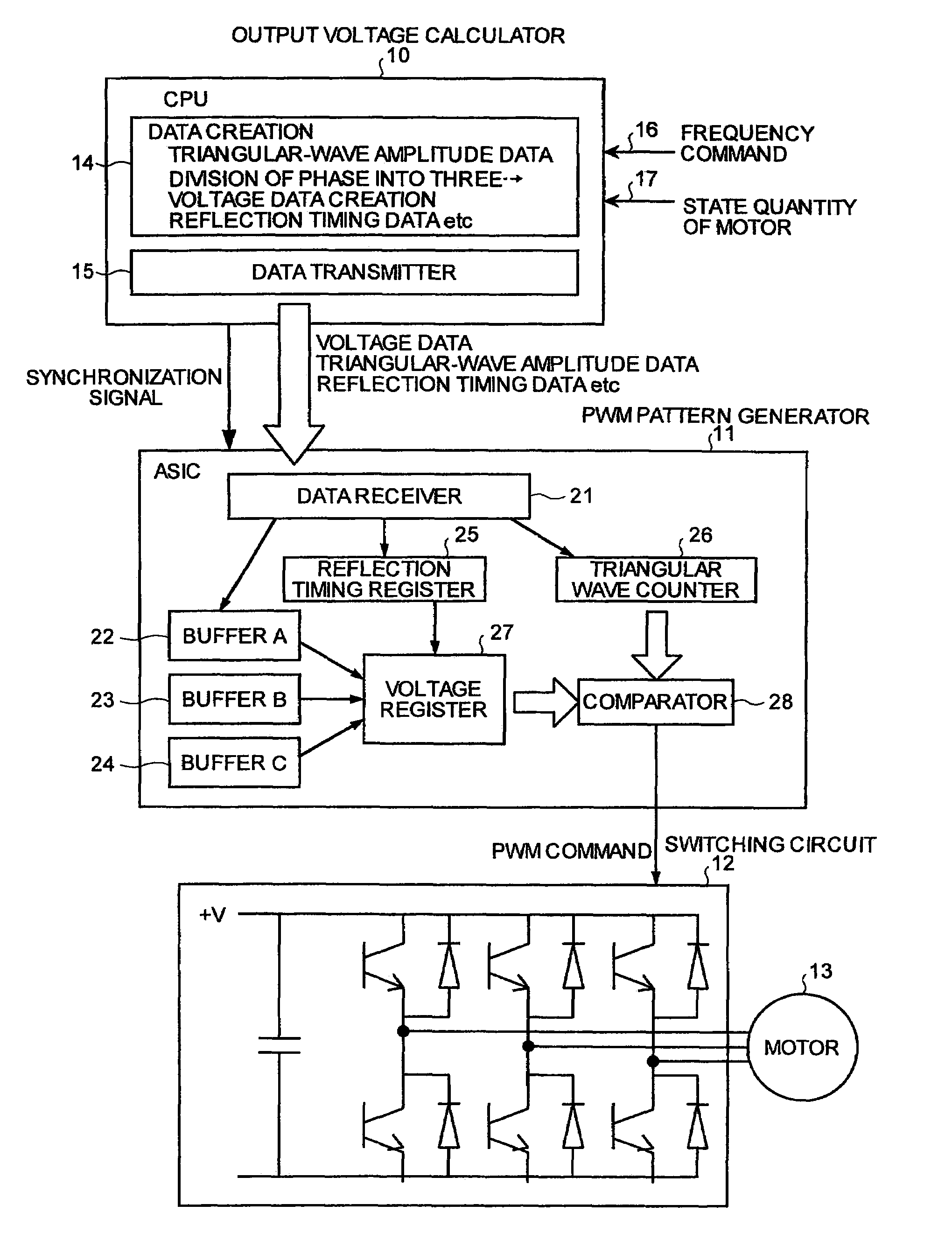
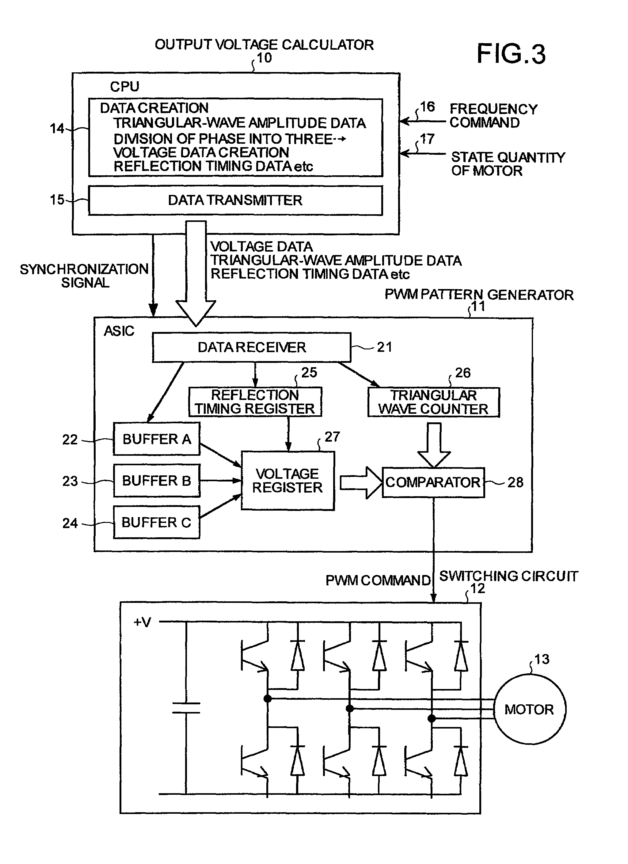
[0021]FIG. 3 is a block diagram of the configuration of an inverter device according to one embodiment of the present invention. The inverter device of FIG. 3 includes an output voltage calculator 10, a PWM pattern generator 11 that receives an output of the output voltage calculator 10, and a switching circuit 12 that receives an output of the PWM pattern generator 11. The switching circuit 12 is connected with a motor (an induction motor or a synchronous motor) 13. The motor 13 is shown here as a three-phase motor.

[0022]The output voltage calculator 10 includes a central processing unit (hereinafter, “CPU”) 14 that creates various types of data, and a data transmitter 15 being an interface for transmitting the data created to the PWM pattern generator 11.

[0023]To the CPU 14, a frequency command 16 for driving the motor 13 and a st...


PUM


Abstract

A CPU calculates, based on a frequency command value for driving a motor and on a state quantity of the motor, an output-voltage command value in which only the phase advances while amplitude is constant in each calculation period, without reducing the calculation period. An ASIC reflects the output-voltage command value in a triangular wave signal in a time-series order to compare with each other, and outputs a PWM signal to a switching circuit. Thus, a waveform of an output voltage is made close to a sine wave irrespective of an output frequency being high or low, and a processing load of the CPU is reduced.

Description

TECHNICAL FIELD[0001]The present invention relates to an inverter device for driving a motor at an arbitrary frequency.BACKGROUND ART[0002]An inverter device for driving a motor such as an induction motor and a synchronous motor generally includes an output-voltage calculating unit that calculates an output voltage command in each calculation period, based on a frequency command value input to drive a motor and a state quantity of the motor detected; a PWM-pattern generating unit that outputs a PWM (pulse-width modulation) signal based on a comparison between an output-voltage command value output by the output-voltage calculating unit and a triangular wave signal; and a switching unit that switches a direct voltage according to the PWM signal output by the PWM-pattern generating unit and supplies an alternating voltage with a predetermined frequency to the motor. However, the waveform of the alternating voltage output by the switching unit becomes a staircase pattern, and hence, fo...

Claims


Application Information

Patent Timeline
Patent Type & Authority Patents(United States)
IPC IPC(8): G05B11/28G05B15/00H02M7/5387H02M7/5395H02P27/08
CPCH02M7/53873H02P27/08H02M7/5395
Inventor YOSHIMURA, MANABUKAITANI, TOSHIYUKI
Owner MITSUBISHI ELECTRIC CORP
Why Eureka
Try Eureka