Touch panel for display device

a display device and touch panel technology, applied in the field of touch panel for display devices, can solve the problems of complex circuit structure, -type touch panel, and related art resistive-type touch panel not suitably integrated with all types of display devices

Inactive Publication Date: 2008-10-14
LG DISPLAY CO LTD
View PDF14 Cites 115 Cited by
  • Summary
  • Abstract
  • Description
  • Claims
  • Application Information

AI Technical Summary

Benefits of technology

[0028]An advantage of the present invention provides a touch panel for a display device, wherein benefits of resistive-type and EM-type touch panels are integrated into a single system, thereby obtaining advantageous characteristics such as detecting a contact point via hovering above, and direct contact with, the touch panel.
[0029]Additional features and advantages of the invention will be set forth in the description which follows, and in part will be apparent from the description, or may be learned by practice of the invention. These and other advantages of the invention will be realized and attained by the structure particularly pointed out in the written description and claims hereof as well as the appended drawings.
[0030]To achieve these and other advantages and in accordance with the purpose of the present invention, as embodied and broadly described, a touch panel for a display device may, for example, include a display device for displaying a picture image according; a resistive-type touch panel arranged above the display device; and an EM-type touch panel arranged below the display device.
[0031]In one aspect of the present invention, the display device may be provided as an LCD device, wherein the LCD device may, for example, include an LCD panel having lower and upper substrates bonded to each other and spaced apart from each other at a uniform distance, and a liquid crystal layer arranged between the lower and upper substrates; lower and upper polarizing plates respectively adhering to lower surface and upper surfaces of the LCD panel for polarizing light; and a backlight arranged below the LCD panel for substantially uniformily emitting light toward the lower surface of the LCD panel.
[0032]In another aspect of the present invention, the resistive-type touch panel may, for example, include upper and lower substrates each having transparent electrodes arranged thereon and patterned spacers arranged between the upper and lower substrates.
[0033]In still another aspect of the present invention, the upper and lower substrates may be bonded to each other via an adhesive material provided in a dead space region of the resistive-type touch panel.

Problems solved by technology

However, the related art resistive-type touch panels are not suitably integrated with all types of display devices.
The related art EM-type touch panel, however, has a complex circuit structure and is difficult to integrate with existing liquid crystal display modules (LCMs).
Moreover, related art EM-type touch panels respond only to corresponding stylus pens, thereby making it difficult apply EM-type touch panels for use in certain applications (e.g., industrial fields).

Method used


Image

  • Touch panel for display device
  • Touch panel for display device
  • Touch panel for display device

Examples


Embodiment Construction

[0052]Reference will now be made in detail to embodiments of the present invention, examples of which are illustrated in the accompanying drawings. Wherever possible, the same reference numbers will be used throughout the drawings to refer to the same or like parts.

[0053]As shown in the Figures, the touch panel according to the principles of the present invention may be integrated with a display device such as a liquid crystal display (LCD) device. It will be readily appreciated, however, that the concepts of the present invention may be readily extended to integrate the touch panel with substantially any type of display device such as a Cathode Ray Tube (CRT), Plasma Display Panel (PDP), Electro Luminescent Display (ELD), Vacuum Fluorescent Display (VFD), and the like.

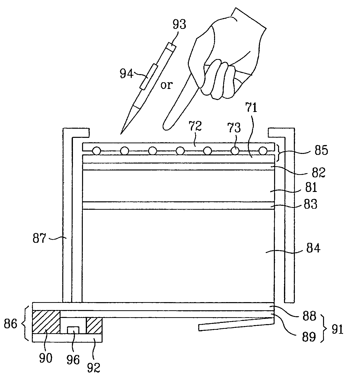
[0054]FIG. 5 illustrates a cross-sectional view of a resistive-type touch panel according to principles of the present invention.

[0055]Referring to FIG. 5, the resistive-type touch panel 85 may, for example, include a...


PUM

PropertyMeasurementUnit
thicknessaaaaaaaaaa
distanceaaaaaaaaaa
distanceaaaaaaaaaa

Abstract

A touch panel for a display device integrates functionality provided by resistive-type and EM-type touch panels. The touch panel is integrated with the display device and includes a resisitve-type touch panel arranged above the display device and an EM-type touch panel arranged below the display device.

Description

[0001]This application claims the benefit of the Korean Application No. P2002-70794 filed on Nov. 14, 2002, which is hereby incorporated by reference for all purposes as if fully set forth herein.BACKGROUND OF THE INVENTION[0002]1. Field of the Invention[0003]The present invention relates to touch panels for display devices. More particularly, the present invention relates to combination resistive-type and electromagnetic type touch panels for display devices.[0004]2. Discussion of the Related Art[0005]Touch panels have been developed as a means of efficiently interfacing with electronic devices via a display surface. For example, users may input desired information using a touch panel integrated with a display device while watching images displayed by the display device. Allowing users to input desired information to an electronic device via a display surface, touch panels substantially reduce or eliminate the need for other types of input devices (e.g., keyboards, mice, remote con...

Claims


Application Information

Patent Timeline
Patent Type & Authority Patents(United States)
IPC IPC(8): G06F3/041G06F3/033G06K11/06G08C21/00G06F3/045G06F3/042G06F3/043G02F1/1333G06F3/046
CPCG06F3/045G06F3/046G06F2203/04104G02F1/1333
Inventor HONG, HEE JUNGKONG, NAM YONGYOU, TAE HOPARK, HEE JEONGLEE, CHEON SUCK
Owner LG DISPLAY CO LTD
Why Eureka
Try Eureka